A Quote from Andrew and me....Finally build and fit a speaker delay circuit that also detects excessive output offset and triggers that output switch. Now you can fairly safely attach your expensive speakers.
Go with dc and over heat safe cut off aswel ie a simple thermal trip can be wired in and cut the whole amp dead till it cools down and re-powers up again.
Good to see things back to normal.. in some cases when amplifiers take a short to there o/p stage you can bet it's knocked out the long tail input transistors as theses are in the nfb path.
still it's been a epic battle with this amplifier and we've all added valid comments to get it back on track.. it's just the terms used such as vas, tail pairs that get's you confused.
Regards A.
Last edited:
Hi Anthony,
Yes you are right. It has been quite a journey on this one. All of you have been a tremendous help. You are also right in that I still don't quite understand what exactly makes up a VAS and though I know which devices are the long tail on this amp I still struggle to pick them out on other designs. Hopefully I will eventually get a grasp on it.
I should learn to build a speaker protection circuit. None of my amps have them yet. If I can get this amp to sound as good as it is supposed to, I will want to use it more often and that will mean protecting my speakers.
Blessings, Terry
Terry,
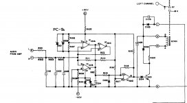
I sent you an email with the DH500 manual attached. In the meantime, here is a copy of that part of the schematic.
http://www.hafler.com/techsupport/pdf/DH-500_amp_man.pdf
I sent you an email with the DH500 manual attached. In the meantime, here is a copy of that part of the schematic.
http://www.hafler.com/techsupport/pdf/DH-500_amp_man.pdf
Attachments
Last edited:
leach superamp
Amen to that one
Well done again.
Remember, experience is expensive. (I like that saying) Mistakes are the best way to learn. If you don't make mistakes you'll never make anything.
Amen to that one
Amen to that one
Glad you like that one. Its my philosophy in this hobby. That way I never get upset blowing something up.
Bob's speaker protection circuit can be upgraded with led state ie green led for ok and fault detection red.. once built these unit can be checked via small dc battery of 1.5 vdc and the relay should act fast and de-activate.. have a read on that audio book as it may have some dc protect circuits to choose..
OK, Amptech, as an exercise, let's add the LED indicators.
The green seems easy - LED + current limiting resistor across relay terminals. When everything is fine, the relay is activated there is enough voltage there to light the LED.
The fault signal seems a bit more problematic. In a fault condition, the output of IC101D goes negative. Would it work to connect that signal to the base of a PNP transistor with emitter connected to the local positive rail with LED and resistor connected between it and the local negative rail? Sort of an upside down Q101/R120 with an LED substituted for the relay. If that does signal a fault, would it show a fault during the turn on delay?
In my DH500 the timing circuit resets quickly with power interruptions. I haven't determined if the rails collapse quickly or power off results in a DC fluctuation. If it is because the rails collapse quickly, do we need something else to ensure that our protection circuit trips on power interruptions? AndrewT advocates using a 555 based timer in soft start applications. Would it make sense to do that here? Then we'd have to mix the timer output and fault detection output.
EDIT: Ahh, the quick cutout is due to the relay being powered by its own rectifier without a capacitive filter. Therefore as soon as the power is pulled the relay trips.
Hope you don't mind a deviation from the main point of this thread, Terry.
Last edited:
Better not use the half wave supply for the relay from the transformer. The transformers don't like it.
I had done it with this circuit for my amp and finding that one of the transformers(had two 40V trafos) that supplied the relay was getting much hotter. Put another transformer with full wave rectification.
Gajanan Phadte
I had done it with this circuit for my amp and finding that one of the transformers(had two 40V trafos) that supplied the relay was getting much hotter. Put another transformer with full wave rectification.
Gajanan Phadte
Gajanan, I suspect that an imbalanced current because you're only using one leg may have been part of your heat issue. It could also be that your relay drew a lot of current. On the other hand, my DH-500 has been in near daily use for several hours a day and is still going strong.
If you decide to use a separate transformer to power the relay, use the whole winding - if center tapped, go full wave, if it's a single ended winding half wave should be fine.
If you decide to use a separate transformer to power the relay, use the whole winding - if center tapped, go full wave, if it's a single ended winding half wave should be fine.
I like the idea of using a separate small transformer. You can put all the supervisor circuitry on it (DC protect/pop muting, temp sense/fan control, soft start control, or whatever you dream up) and all that will continue to function regardless of a fault condition in the amp or its power supply. When the little PC mount trafos go for $3 a pop on the surplus market, why not use them?
It's a matter of preference, IMHO. I always seem to find myself real estate limited within the chassis. If I can use a single transformer, means I am able to do things like dual PSUs, more capacitance and regulated front end supplies in there.
In this case, the relay contacts open when power is removed or a fault exists, so it doesn't really matter if the sensor circuit continues to have power. You could also resolve Gajanan's issue with the addition of another diode and have full wave power to the relay. It might mean changing the current limiting resistor a bit, but the relay power would be delivered symmetrically by the transformer.
In this case, the relay contacts open when power is removed or a fault exists, so it doesn't really matter if the sensor circuit continues to have power. You could also resolve Gajanan's issue with the addition of another diode and have full wave power to the relay. It might mean changing the current limiting resistor a bit, but the relay power would be delivered symmetrically by the transformer.
I would like to obtain Leach's Low TIM and SUPERAMP PCB's
Does anyone know of a source for Professor Leach's Low TIM and SUPERAMP
PCB's? Let me know. I would like to build both of these as a tribute to Professor Leach. I hope his school keeps his WEB site active and expands on it as a
place for power amplifier designs.
Does anyone know of a source for Professor Leach's Low TIM and SUPERAMP
PCB's? Let me know. I would like to build both of these as a tribute to Professor Leach. I hope his school keeps his WEB site active and expands on it as a
place for power amplifier designs.
Bob, would agree there, or even just add a green led tapped with relay also the the dropper resistors for the plus and minus rails would need a adjustment due to heat waste even 5w here. 90 odd volts being dropped down to 15volts to operate that circuit.
I've seen plenty of circuits that use ac loss built in that deactivate quicker instead of waiting for the dc rails to discharge and the relay turning off slower.
Any way back to topic good news that Terry's amp is running...
I've seen plenty of circuits that use ac loss built in that deactivate quicker instead of waiting for the dc rails to discharge and the relay turning off slower.
Any way back to topic good news that Terry's amp is running...
Last edited:
I played it all day today. Sounds a little too good. Shows all the warts in some of the recordings I have. The jazz is stellar with this amp.
For speaker protection, I have also been looking at some of Randy Slone's circuits. Do you think Hafler just ran this one on 90V because that is what the PS is? Seems it can be run on much less.
Thanks, Terry
For speaker protection, I have also been looking at some of Randy Slone's circuits. Do you think Hafler just ran this one on 90V because that is what the PS is? Seems it can be run on much less.
Thanks, Terry
leach superamp
Slone's speaker protection circuit is easy to install plus offers very effective led indication via transistor control switching, it can be built on strip board or pcb plus use 24 volt with 10 amp relay. If you have space you can use small transformer or if not adjust the dropper resistor with it's zener reg cicuit if tapping off amps rails..
Great news all is up and running.
Regards A.
I played it all day today. Sounds a little too good. Shows all the warts in some of the recordings I have. The jazz is stellar with this amp.
For speaker protection, I have also been looking at some of Randy Slone's circuits. Do you think Hafler just ran this one on 90V because that is what the PS is? Seems it can be run on much less.
Thanks, Terry
Slone's speaker protection circuit is easy to install plus offers very effective led indication via transistor control switching, it can be built on strip board or pcb plus use 24 volt with 10 amp relay. If you have space you can use small transformer or if not adjust the dropper resistor with it's zener reg cicuit if tapping off amps rails..
Great news all is up and running
.Regards A.
- Status
- This old topic is closed. If you want to reopen this topic, contact a moderator using the "Report Post" button.
- Home
- Amplifiers
- Solid State
- Leach Superamp, round 2