When measured in the reality: A typical TL do not have a negative onset IR slope. HR turns it upside down thus do not depict the 'IR' reality for 99...% of a TL build when in TH screen mode or in OD mode or in 'Nd' too.
The important part here is that TH, Nd and Od are all the same, none of them need polarity reversed (wrt the others) to have the same behavior.
As quoted from post 77:
For the purposes of calculating impulse response, Hornresp assumes the convention that the side of the driver diaphragm facing the horn throat moves towards the throat ...
Like I said, the driver is always facing the same way. I've never checked to see if polarity changes when you use the Vrc and Lrc instead of S1 - S5 and at this point I don't really care, nor do I care about how someone is likely to set up polarity and measure a positive or negative initial spike.
All I care about is that TH, Nd and Od are all the same, the driver is always facing the same way.
Hi just a guy,
For the purposes of calculating impulse response, Hornresp assumes the convention that the side of the driver diaphragm facing the horn throat moves towards the throat, thus increasing the instantaneous pressure on the throat side. This is why the initial spike is negative for both tapped horns and the combined response of an offset driver horn.
Right, the impulse is initially negative for both TH and TL. My point was that since the driver is nowhere near the mouth in a tl and it ALSO has a negative spike to start, the assumption that there is an initial negative pressure at the TH mouth is flawed.
I'm not saying there won't be a LITTLE BIT of negative pressure but if we look back at the original question:
Cone moves away from magnet (which is next to the mouth, usually), and you get positive pressure at the mouth.
Is this what you're telling us?
Time to rethink how I thought tapped horns work, I suspect.
Apparently Chris thought that tapped horns have reverse polarity compared to an untapped equivalent transmission line. As far as I can tell he still hasn't changed his mind on that, so when you said "Hi Chris - You are quite correct." in post 68, this idea what I was objecting to, not the fact that there might be a tiny bit of negative pressure initially due to cone motion direction.
Rest assured, the initial negative spike shown in my tapped horn impulse response example is definitely being generated by the side of the driver diaphragm facing the horn mouth.
Kind regards,
David
Yes, I should have changed that but due to forum rules there was no time left to edit and I would have to make a new post, and I've already posted too much on this issue (which shouldn't need much explanation since it's pretty obvious how this stuff works).
Yes, the initial negative spike is definitely being generated by the mouth side tap. But it has nothing to do with whether the line is tapped or not, the same thing happens in regular untapped transmission lines too.
Last edited:
Next time I'm just going to keep my big mouth shut. Weltersys accurately described the correct answer to all of this in post 54 in response to Andrew's query and even before Chris asked for clarification:
That's the correct answer, short and sweet, and that's all that really needs to be said on this topic. Stupid me tries to make it a bit easier to understand with imperfect analogies and now there's 3 whole pages of this...
The correct answer is in post 54. That's probably where this should have ended.
The driver diaphragm pushing towards the TH throat (S2) creates positive pressure at the mouth, as in a FLH.
That's the correct answer, short and sweet, and that's all that really needs to be said on this topic. Stupid me tries to make it a bit easier to understand with imperfect analogies and now there's 3 whole pages of this...
The correct answer is in post 54. That's probably where this should have ended.
Stupid me tries to make it a bit easier to understand with imperfect analogies and now there's 3 whole pages of this...
https://i.chzbgr.com/maxW500/6175783680/h8F4894DE/

That's actually pretty funny. Thanks for that, I haven't seen that one before.
I found that a while back when someone on Facebook sent it to me (I'm Canadian as well, I just live in the states) so I use every excuse I can to share it with everyone.I've already posted too much on this issue (which shouldn't need much explanation since it's pretty obvious how this stuff works).
Obvious to who...?
That's how a front loaded horn works, it contains a slug of air and it's always full of that slug of air so flow at the mouth is instantaneous. As soon as the cone moves the air at the mouth is also forced to move. Immediately. Pushing in on the throat causes air to come out the mouth.
A tapped horn works the same way. But since there is an extra source of sound (the mouth side tap) there is a complex interaction between the two sources. Both of the sources still operate in the same fashion (the same as a front loaded horn - pushing in on the throat causes immediate flow out the mouth) but now there are two very distinct sources and those two sources cause very distinct behavior at different frequencies because their position has different effects on impedance.
Hi just a guy,
In what way is the assumption flawed?
(By negative I assume you mean a pressure lower than the static ambient pressure).
I don't believe I ever said that the initial negative spike was unique to a tapped horn. On the contrary, I explained why the Hornresp impulse response for a tapped horn and the combined response of an offset driver transmission line both have an initial negative spike. The output from the transmission line itself, when considered in isolation and not combined with the direct radiation from the front side of the diaphragm, will have an initial positive spike.
Kind regards,
David
the assumption that there is an initial negative pressure at the TH mouth is flawed.
In what way is the assumption flawed?
(By negative I assume you mean a pressure lower than the static ambient pressure).
Yes, the initial negative spike is definitely being generated by the mouth side tap. But it has nothing to do with whether the line is tapped or not, the same thing happens in regular untapped transmission lines too.
I don't believe I ever said that the initial negative spike was unique to a tapped horn. On the contrary, I explained why the Hornresp impulse response for a tapped horn and the combined response of an offset driver transmission line both have an initial negative spike. The output from the transmission line itself, when considered in isolation and not combined with the direct radiation from the front side of the diaphragm, will have an initial positive spike.
Kind regards,
David
Last edited:
Obvious to who...?
It's obvious to me. I'm sure it's obvious to you too. And I think it's obvious to weltersys. I can't speak for anyone else.
You can throw that quote back at me if you want but I already admitted it was an imperfect analogy when weltersys questioned it a long time ago and I already explained why I used it.
This started out as a very simple question. Andrew said:
Is this confirming that the phase of the rear radiation into S2 is the dominant output of the TH? i.e. much as a front loaded horn where the phase into the throat is the dominant output.
Then Chris said:
Cone moves away from magnet (which is next to the mouth, usually), and you get positive pressure at the mouth.
Is this what you're telling us?
Time to rethink how I thought tapped horns work, I suspect.
Weltersys gave the correct answer. Then I used a bad analogy to try to make the concept easier to understand. I shouldn't have done that and I'm sorry.
But you have to understand that when I said "immediately" in that quote I was trying to refute the idea that tapped horns have reverse polarity compared to an untapped equivalent tl. "Immediately" was a very bad word to use, take that word out and there's nothing wrong with what I said. I know very well that there is a delay between the throat and the mouth, I know very well that this type of line is usually digitally delayed about 1 ms per foot of line length. I was trying to make the subject fit the analogy when it really doesn't fit and that was a big mistake. I thought an analogy would be simpler than explaining in detail that tapped horns have a very complex interaction and summing depending on frequency, phase and impedance but overall act mainly as a transmission line. When weltersys called me out on this use of the word "immediately", I immediately admitted he was correct. So why bring this up again?
In what way is the assumption flawed?
(By negative I assume you mean a pressure lower than the static ambient pressure).
I already explained this in detail. The initial negative impulse spike is the same for a TH or an untapped TL (in which the driver is nowhere near the mouth). My reasoning here is that they both work the same in this respect and even if there is a small quick burst of negative pressure at the tapped horn's mouth due to the direction of cone motion and due to proximity to the mouth, it's still behaving very much like a TL. In other words, that quick negative impulse does not equate to reverse polarity.
When you drop in on the conversation out of nowhere and your first comment is "Hi Chris, You are quite correct.", it makes me think you are backing up the idea from the original question that tapped horns have reverse polarity (compared to an equivalent untapped tl) - because I'm pretty sure this (reverse polarity) is exactly what he was getting at with the comment that inspired your answer. At this point I'm pretty sure that's not what you are trying to say, and if not I guess the assumption was not really flawed.
As far as I can tell I've made two mistakes - I used the word "immediately" inappropriately and I think I misconstrued the point of what you were trying to say when you responded to Chris.
The fact remains that the original question was answered way back in post 54. Tapped horns do not have reverse polarity compared to an equivalent untapped tl - push in on the throat and air comes out the mouth.
Last edited:
Hi just a guy,
I was simply responding to the statement made by Chris in Post #60, which was included in my reply as a quote. If I had been addressing the original question I would have included that as a quote instead.
Kind regards,
David
When you drop in on the conversation out of nowhere and your first comment is "Hi Chris, You are quite correct.", it makes me think you are backing up the idea from the original question that tapped horns have reverse polarity (compared to an equivalent untapped tl)
I was simply responding to the statement made by Chris in Post #60, which was included in my reply as a quote. If I had been addressing the original question I would have included that as a quote instead.
Kind regards,
David
Hi,
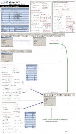
Some forgotten simulations that is a continuation of post #36( My view of comparing the TH and the FLH when preserving BW over SPL) and a new suggestion of an T-TQWT.
b
Some forgotten simulations that is a continuation of post #36( My view of comparing the TH and the FLH when preserving BW over SPL) and a new suggestion of an T-TQWT.
b
Attachments
Thanks for explaining post 36, now I have a better idea of what you did there, previously it didn't make any sense to me at all.
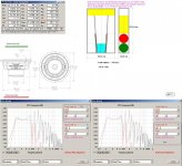
Now that I can see what you did, I can see that you castrated my design with inappropriate filters. Both the low and highpass filters were set too low in frequency.
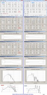
Here's a pic showing our different approaches to filtering this flh. The two pics in the top row show your approach and the two pics in the bottom row show my approach (and I only spent a couple of minutes on this so it could probably be improved a bit). Both shown at xmax. Your approach can only handle 1475 watts while mine can take 3500, the only difference for this discrepancy due to the high pass filter.

My approach gives ~3db more across most of the bandwidth (but only about 2 db more at the very low end) AND more bandwidth on the top end.
As previously mentioned, 3500 watts (across 4 drivers) is more than they are rated for but as I explained previously I don't think that's a problem at all. Excerpt from post 13:
The part in bold should read "more than 100 percent". And if 2 of the drivers were flipped (2 motors in the chamber, 2 motors in the throat), it would be almost 5x larger than the Lab chamber (per chambered motor).
And finally, here's post 15 again, which speaks to the thermal capability of the TC Sounds drivers as measured by data-bass.com:
None of this matters much since the OP doesn't have 3500 watts and doesn't want to upgrade but I do feel that you dramatically misrepresented the capability of my design with odd filter choices.
Now that I can see what you did, I can see that you castrated my design with inappropriate filters. Both the low and highpass filters were set too low in frequency.
Here's a pic showing our different approaches to filtering this flh. The two pics in the top row show your approach and the two pics in the bottom row show my approach (and I only spent a couple of minutes on this so it could probably be improved a bit). Both shown at xmax. Your approach can only handle 1475 watts while mine can take 3500, the only difference for this discrepancy due to the high pass filter.
My approach gives ~3db more across most of the bandwidth (but only about 2 db more at the very low end) AND more bandwidth on the top end.
As previously mentioned, 3500 watts (across 4 drivers) is more than they are rated for but as I explained previously I don't think that's a problem at all. Excerpt from post 13:
To address the power concerns head on, I've never burned a sub. Ever. Even when I try to reach pmax and xmax at the same time in my sims it ALWAYS sounds bad long before it burns. Even when I exceed pmax before hitting xmax in my sims it ALWAYS sounds bad before I have thermal issues. In other words, I've always had excursion issues and never thermal problems. Now if you have a clueless dj that keeps turning it up well past the point that it starts to sound bad that's another story completely...
My sim is shown at 3500 watts rms per cab (875 watts per driver). The drivers are rated at 500 rms (2000 peak) and I think they could handle the power I've shown them at with minimal thermal compression. As you pointed out awhile back, assuming fairly dynamic music the drivers only get a fraction of the amp's full output capability most of the time.
Chamber size in this design is 200 liters. This is almost 5x larger than the Labhorn rear chamber. This design has twice as many drivers though, so cut this larger design in half and then driver for driver it's almost 2.5x larger than the Labhorn rear chamber. To be painfully clear, the Lab has about 21 liters per driver and this design has 50 liters per driver. Also, this design is tuned almost an octave lower than the Lab, which means much more cone movement, which equates to a lot more fan action cooling the coils.
The Labhorn is obviously not the best example of a thermally controlled environment but compared to this design they are not even close. You have almost 50 percent more chamber PER DRIVER in this design compared to the Lab and a lot more cone movement to help cool the drivers. So I don't think calling the chamber "tiny" and "an oven" is really fair. Besides, the chamber could be increased by 25 liters without causing any problems but I didn't do that because I was trying to keep it the same size as the tapped horn sim presented in post #1. Also, the design could be tuned even lower than shown, requiring a much larger chamber if that was desired.
The part in bold should read "more than 100 percent". And if 2 of the drivers were flipped (2 motors in the chamber, 2 motors in the throat), it would be almost 5x larger than the Lab chamber (per chambered motor).
And finally, here's post 15 again, which speaks to the thermal capability of the TC Sounds drivers as measured by data-bass.com:
I checked to see if Josh at data-bass.com had tested this driver. Unfortunately he had not. The only 12 inch tc driver he had tested was the lmsr. I believe it's this one.
TC Sounds LMS-R 12" DVC Subwoofer 293-658
So as you can see the manufacturer's specs say it's rated for 1000 watts rms.
Data-bass.com did not actually state how many watts they tested this driver with on any page that I could find but they did measure Re at 4.15 ohms here:
Data-Bass
And measured spl with voltages up to 143 volts here (second graph - long term power compression):
Data-Bass
I used Hornresp to do the math for me since I'm very very bad at math.
143 volts at 4.15 ohms is very close to 5000 watts rms. As anyone might expect, there was significant power compression at this level.
But at 101 volts there was very minimal power compression. That's right around 2500 watts rms.
That's not so bad for a driver rated at 1000 watts rms. So if the little tc epic has anything in common with it's big lmsr brother you can see why I'm not too worried about power compression.
None of this matters much since the OP doesn't have 3500 watts and doesn't want to upgrade but I do feel that you dramatically misrepresented the capability of my design with odd filter choices.
Last edited:
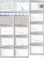
The sim above assume 1 cab and as expected it looks even better with 3 cabs and allows different filters and smoother response. Better low end, smoother response and more usable bandwidth on the top end. Could still raise the low pass filter even higher if desired for more high end bandwidth. 3 cabs shown below, 3500 watts each.

Last edited:
The check came through from my customer, I'm sitting on 10 of the 12 TC Epic 12s (the last 2 are back ordered to beginning of october dammit) and a stack of 3/4" MDF and 3/4" baltic birch.
I settled on the 3 segment tapped horn approach to design and modeling, as per TB46 suggestion, with some final adjustments for the space available & the internal space eaten up by bracing. With a touch of tweaking to the venue (cutting a notch in the bar top on one side) I was able to increase available space dimensions to 98 x 43 x 18 so the cabinet external dimensions will be 96 x 42.5 x 17.5.
I plan to build one out of each material simply to satisfy myself once and for all as to the sonic differences between birch and MDF and then build the remaining 2 for installation out of whatever wins the performance shootout...
started the cuts last night, continuing today. I'll post finals of the design, pix, and performance data when it is done.
Wish me luck
Last edited:
Hi just a guy,
In what way is the assumption flawed?
(By negative I assume you mean a pressure lower than the static ambient pressure).
I don't believe I ever said that the initial negative spike was unique to a tapped horn. On the contrary, I explained why the Hornresp impulse response for a tapped horn and the combined response of an offset driver transmission line both have an initial negative spike. The output from the transmission line itself, when considered in isolation and not combined with the direct radiation from the front side of the diaphragm, will have an initial positive spike.
Kind regards,
David
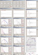
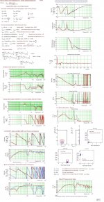
The problem with all these horrible-looking impulse response plots is that they're theoretically correct but largely irrelevant to a bass horn, tapped or not...
They show what happens when you fire a wideband impulse into the driver -- in other words, a signal with frequency content up to several kHz. Unsurprisingly the result is terrible, with lots of narrow reversing polarity spikes in the time domain and horrible peaks and dips in the frequency response -- which would be relevant if you tried to use the tapped horn up to several kHz, which nobody does. The spikes are narrow only because the signal bandwidth is large.
If you bandlimit the signal -- as would be done in real life with a fast-slope crossover -- the picture changes completely, and both impulse and frequency responses smooth out greatly. If this wasn't the case all tapped horns would sound terrible no matter how well they're set up, which is clearly not the case.
The error being made is the same as people sometimes make when measuring electrical reflections in PCBs/cables, they fire a signal with very fast risetime into it (because the test equipment can) and see horrible results, which are not borne out in actual use with slower risetime signals. The key is that you should always measure with a signal whose bandwidth and risetime matches that of the signal that it will see in real life.
It's exactly the same issue as the discussion about rounded corners or corner reflectors in a bass horn "helping" the sound waves reflect round the bends -- true for high frequencies but not for bass ones.
Finish...these are for perm install, so they won't need road rash protection...figured paint du jour, inside & out...If someone has a recommendation that comes with reasons that will really affect the performance or lifespan for cabinets that will spend their life installed indoors & being heard but not seen, fire away...
Also ensure there's some kind of grill covering the driver cone.
If a can gets sucked in there and starts bouncing off the cone, you'll lose the driver pretty quick.
I work Union club nights, and see this sort of thing quite often. A belt (buckle) tore one of our 18"s apart recently, and the re-cone wasn't cheap.
Chris
If a can gets sucked in there and starts bouncing off the cone, you'll lose the driver pretty quick.
I work Union club nights, and see this sort of thing quite often. A belt (buckle) tore one of our 18"s apart recently, and the re-cone wasn't cheap.
Chris
- Status
- This old topic is closed. If you want to reopen this topic, contact a moderator using the "Report Post" button.
- Home
- Loudspeakers
- Subwoofers
- latest study in excess