Hi,
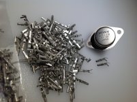
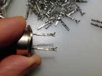
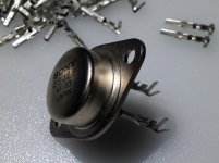
I pulled the attached TO-3 part from a thick salvaged heatsink and
noticed there appears to be extension pins. I want to use the
same on a 2sk82. Would anyone know where I can get these
extension pins?
Thanks,
Dennis
Hi Dennis
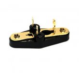
You can use TO-3 socket as well
")
Best regards
http://www.ebay.com/itm/10sets-Bake...aa162f0&pid=100005&rk=1&rkt=3&sd=130328755206
Attachments
Last edited:
Hi Christophe,
Thanks. In my case, the heatsink I want to use is quite thick and the
pins on the To-3 part doesn't quite extend pass the base plate.
Cheers,
Dennis
Hi Dennis
Good news !
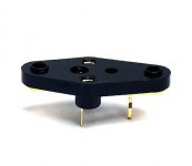
I have lot of special for TO-3 transistors extensions by 10 mm = 0,393 inch more.
It's what you need ? Very easy to solder btw.
How many pieces ? If you interested simply PM me.

Christophe
Attachments
Last edited:
@ Diyers
In L'Amp first capacitors after audio signal input are 10 uF non polarized type.
After visualised this video i think try experiment if this realy work in sit amp.
I see inside of my old Hiraga amplifier Wima red film caps have (+) write by hand with pencil on non polarized ! ?
What Diyers opinions ?
https://www.youtube.com/watch?v=BnR_DLd1PDI
You can use a smaller inductor, but not too small. Is good to have margin because this inductor will shunt current to supply, and inductively. So this will add unwanted distortions. Instead 3mH I think some 10-12mH will suffice for this 400Hz work, and some crossover inductors in market have this value.The 1000 watt package is 55 mm in diameter and the 3000 watt device is 76 mm in diameter. I am not sure if the 3000 watt device was actually available as a few of these
SITS listed in the Token data sheets were just proposed new devices and never produced other than as early samples.
Now to practical maters. If I just wanted an inductor loaded amp to just cover above 400hz would I be able to use a small inductor say around 3mh instead of that 110 mh one Michael Rothacher used in his amp ? Wouldn't a 3mh inductor give a 6 db per octive crossover point at ~400 hz for an 8 ohm speaker if the impedence curve was rather flat.
...or if you use horn/hi eff speakers with low/moderate volumes, you can experiment with output inductor as crossover.
They are not from the socket.Those sure look like they came from a TO-3 socket...
oops! never mind...
Don't use pins extension if you use TO-3 socket...
Best regards
Hi Christophe,
Are those Molex connector pins?
Thanks,
Dennis
Hi Dennis
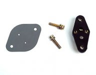
Visibly yes is Molex connectors inside part.
Like you see on my photos they can do the job
but other solutions are better or equal.
Connectors i ready have on my table without buy " that one's "
Greetings
The story is i bought them like a part of big box of new old stock components without knowing his utility.
Always guessing they was made for TO-3

I have used stranded hook up wire soldered to TO-3 parts with heat shrink insulation to insulate inside the heat shrink holes. If I have long gate wires between drive source and gate I put the gate stopper resistor right at the gate pin and heat shrink over the resistor and wire. I trust the soldered connection more than a socket pin. Of course for thick heat sinks you have to make these connections before mounting the part to the sink.
Last edited:
I have used stranded hook up wire soldered to TO-3 parts with heat shrink insulation to insulate inside the heat shrink holes. If I have long gate wires between drive source and gate I put the gate stopper resistor right at the gate pin and heat shrink over the resistor and wire. I trust the soldered connection more than a socket pin. Of course for thick heat sinks you have to make these connections before mounting the part to the sink.
Hi my friend Mike
Yes simple and efficient solution
Btw i use Puffin Pro Browser software on Mac
so i can show many photos on DiyAudio Forum.
Greetings and have a nice sunday
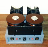
Today i am one very unhappy diy man.
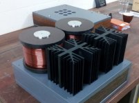
After conversion of my 2sk82 L'amp from fixed bias to self bias (as per post 2355), the left channel SIT died after about 3 hours operation.
I have no clue of what could have gone wrong. Both SITs had dialled in close to each other with bias voltages of -6.2 and -6.5 V (1.59 amps 1.66 amps).
I have no spare 2sk82 KD33 left. I had bought an extra pair from Acronman, but used it for LuminAria (who would have thought that Michel would come up with another design for these SITs?)
If one of you is ready to sell a pair of KD33 types, please let me know.
The pictures show L'amp and LuminAria in the back and the simple inside of L'amp.
Power supply is external (cLCrC)
Attachments
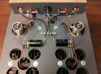
From your photos and 2355 schematic the cap should be at source not the drain plus yours source resistor to ground is missing or its next to sit?
You are totally right. How could i get that cap connection wrong? But it wouldn't explain the failure of the SIT.
As for the resistors, they are big 50 watters hidden between the two heatsinks at the back.
Many thanks for your help.
Attachments
Yes, the cap needs to be at the junction of the source and source resistor. Do you have a schematic sketch of how you connected everything? It's a little hard to tell what the sit connections are in the photo.
Many thanks for your reply. I did use the schematic of post 2355 but made the mistake you mentioned of connecting the cap to the drain. I shall change that asap and see what the remaining SIT shall say.
- Home
- Amplifiers
- Pass Labs
- L'Amp: A simple SIT Amp