If one of you is ready to sell a pair of KD33 types, please let me know.
I think I have a set of these I never have put to use...

Yes, with the cap at the drain you would still need to bypass the source resistor. That's why I moved it to source and adjusted the value. Perhaps when you removed the fixed bias voltage source something funny happened on the gate connections?
Fully agree. I also suspect something happened at the gate connection. Maybe suddenly the gate had no longer a connection to ground and the amps started going high?
Auto bias is the safest principle with the minimum parts (At the expense of about 20 watts in the present case...) and i would not question it.
I would really love to keep this amp. I put quite some effort into it.
I think I have a set of these I never have put to use...
Hello Skorpio
Thats good news. KD33 types are probably the only ones that we can reasonably use with auto bias. The other types require higher bias voltages and this will result in too much heat dissipation at the source resistors. Or am i wrong?
I shall send you a private mail.
Many thanks
The pictures show L'amp and LuminAria in the back and the simple inside of L'amp.
Power supply is external (cLCrC)/QUOTE]
Hi Jostwid,
sorry for interrupting the discussion...
Your Amp really looks nice and i hope you get it singing again real soon.
could you please tell us more about the chokes you use as the load?
where did you get them, or did you build them yourself ?
TIA and cheerio,
Balou
Attachments

The pictures show L'amp and LuminAria in the back and the simple inside of L'amp.
Power supply is external (cLCrC)/QUOTE]
Hi Jostwid,
sorry for interrupting the discussion...
Your Amp really looks nice and i hope you get it singing again real soon.
could you please tell us more about the chokes you use as the load?
where did you get them, or did you build them yourself ?
TIA and cheerio,
Balou
Welcome
I calculated the inductors with with "Air Core Inductor Designer/Calculator", trying to get the most mH for copper weight, with minimum DC resistance. I did the cores myself and had the chokes wound by a lady who runs a transformer winding shop. (Still a lot less expensive than to get the Hammonds shipped and pay taxes on them.)
Data are approximately 75 mH for 2.6 Ohms DC resistance. At first sight this seems to be very low inductance for fullrange use. However comparison with a 150mH choke does not make a big difference for my ears..
My power supply is external and if need be i could add some mH there.. and keep the aesthetics as is.
Best regards
I've been using the still available P-Channel 2SJ28 KF-33 for my autobias experiments and finished amps.
G
More good news! Skorpio did not reply yet to my mail. If by Monday nobody comes forward i shall go for the p_channel option. (And keep in mind Murphie's law: " the fewer the parts, the bigger the chance for a wrong connection)
Jost
Welcome
I calculated the inductors with with "Air Core Inductor Designer/Calculator", trying to get the most mH for copper weight, with minimum DC resistance. I did the cores myself and had the chokes wound by a lady who runs a transformer winding shop. (Still a lot less expensive than to get the Hammonds shipped and pay taxes on them.)
Data are approximately 75 mH for 2.6 Ohms DC resistance. At first sight this seems to be very low inductance for fullrange use. However comparison with a 150mH choke does not make a big difference for my ears..
My power supply is external and if need be i could add some mH there.. and keep the aesthetics as is.
Best regards
thanks alot for the info.!.!
(so..if i want air-core chokes for my L'Amp i have to wind them myself)
... If by Monday nobody comes forward i shall go for the p_channel option ...
I have a single piece of 2SK82 KT-33 that I'm willing to offload, as it's pinch off voltage is rather lower than my stock of KD/E/F-33s.
KT-33 is not very common so you may doubt it's authenticity, but as far as I can tell and measure, it's a real Sony 2SK82 with same trans-conductance as the KD/E/F-33s.
PM me if interested.
Attachments
thanks alot for the info.!.!
(so..if i want air-core chokes for my L'Amp i have to wind them myself)
The Multilayer Air Core calculator from Pronine is more convenient, but the results are the same..
jostwid Placement of coils in crossover networks
channel separation can suffer....
channel separation can suffer....
jostwid Placement of coils in crossover networks
channel separation can suffer....
You are right. But in this case it would only affect the frequencies below appr. 100Hz wouldn't it?
The Multilayer Air Core calculator from Pronine is more convenient, but the results are the same.. View attachment 537119
i found this:
Coil32 - Multilayer coil calculator
looks like exact the same source code...
Yes, with the cap at the drain you would still need to bypass the source resistor. That's why I moved it to source and adjusted the value. Perhaps when you removed the fixed bias voltage source something funny happened on the gate connections?
I did the required changes and while doing that, i discovered a bad solder point that eventually had resulted in cutting the connection from gate via the 47k to ground.
This is what i know and what i am absolutely sure about.
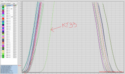
When testing both SITs with the Ohm meter, to my surprise both measured the same.
Followed start up and everything was normal again. Rock solid values during 4 hours and music just fine.
These SITs are solid, almost as triodes
Many thanks again to you and propotki for your hints and advice
Yes and no. I do net get the same results.
jostwid Placement of coils in crossover networks
channel separation can suffer....
Interesting. Had a closer look at the link (by the way i like a lot his work regarding high efficiency speakers)
The placement of the coils in my amp is less than optimal. But at least they are far away from aluminum housing. I almost exlusively use wood.
Now to increase inductance it would be nice to place them side by side, like too wheels. A friend of mine suggested exactly that for aesthetic reasons. But then i had made the box already and there was not enough space on that box and not enough will to make another, bigger one.
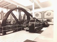
These coils are somewhat monuments of the 19th century Frankenstein and as lying rolls they shine even more.
They are peers of the engines in the picture below.
Attachments
Yes and no. I do net get the same results.
hmm, yeah, i checked that. and the difference is quite substantial
i wonder why is that so...
... and i´m glad to hear your amp playing music again !!
I did the required changes and while doing that, i discovered a bad solder point that eventually had resulted in cutting the connection from gate via the 47k to ground.
This is what i know and what i am absolutely sure about.
When testing both SITs with the Ohm meter, to my surprise both measured the same.
Followed start up and everything was normal again. Rock solid values during 4 hours and music just fine.
These SITs are solid, almost as triodes
Many thanks again to you and propotki for your hints and advice
It's great to hear it gets up running again.
Can you tell the different with adjustable bias and auto bias. I mean which one you like the most.
did you find any strange sound before? great news SIT survived. once i set Vbias in opposite way, so it was biased with +4VI did the required changes and while doing that, i discovered a bad solder point that eventually had resulted in cutting the connection from gate via the 47k to ground.
This is what i know and what i am absolutely sure about.
When testing both SITs with the Ohm meter, to my surprise both measured the same.
Followed start up and everything was normal again. Rock solid values during 4 hours and music just fine.
These SITs are solid, almost as triodes
Many thanks again to you and propotki for your hints and advice
i heard distorted music but i needed about 10sec to realize something was wrong on the circuit, but got no any smokeit seems that SIT can absord human error, to give more courage on experiment.
It's great to hear it gets up running again.
Can you tell the different with adjustable bias and auto bias. I mean which one you like the most.
With regard to music i could not tell. Both sound good.
I have no direct comparison or i would have to make it by doing one channel self bias the other fixed.
There are advantages, disadvantages and constraints for both...
Self bias:
Safest mode for SIT
20 watt higher power consumption (@ 1.63 amps/channel)
Requires extra heatsink for source resistors
Requires higher B+
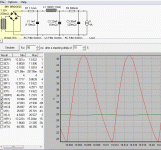
Tuning to find optimum operation point for low distortion requires either change of B+ or source resistor value
(i use a quasi choke input power supply where i can tune the voltage through C1 c.f picture)
Fixed bias:
Not intrinsically safe mode for SIT
Requires additional power supply
Lowest power consumption
Lower B+ (The "standard" 24V supply will do)
Easy to tune for low distortion
Jost
Attachments
- Home
- Amplifiers
- Pass Labs
- L'Amp: A simple SIT Amp