Aren't simulations fun?
When I'm not having convergence problems
") . I always liked Hamming's motto - "The purpose of computing is insight, not numbers."
. I always liked Hamming's motto - "The purpose of computing is insight, not numbers."In the idealized case crossover distortion has nothing to do with the output devices turning off. The logarithmic Vbe modulation between several amps and several micro amps is enough. I still don't get the fixation with "does the output device turn off".
Doesn't even a "real" class A amp do that also?
Have fun ...."playin" . guys..
BTW , mr. wurcer , is "right on the money".
OS
BTW , mr. wurcer , is "right on the money".
In the idealized case crossover distortion has nothing to do with the output devices turning off.
OS
Doesn't even a "real" class A amp do that also?
Yes of course, more is better. Mr Pass knows that.
Amp from post 3 with driver bias resistor removed.
wow , andy and steve on the same page. We still come so close to 0 , what we are attempting is to "rip " the carriers from the bases of the "half" that just switched off ??
Exactly. I think this is just a "does it do what it says on the tin" issue.
Maybe this thread should have been called:
Help me before I Krill someone.
I had planed to just drop this, but couldn't resist ruffling certain feathers one more time.
I threw everything out and started over. Fortunately, parts are cheap in simulation. I even changed the brand of some of the transistors, so these numbers won't be exactly the same as the previous amp.
Working from what has been suggested by Andy, I set the output to 50W into 8 ohms at 10Hz for an almost worst case situation (according to him).
The current flowing in the emitter resistors never drops below 100uA. The current in the base of the driver transistors does not go below 1uA. The total dissipation in the OPS is 38.7W at idle. This is somewhat better than the 131W of the D. Self amp from post 2.
Carrying this one step further, I set the output to 28.3VDC into 8 ohms. The current flowing in the emitter resistors of the "off" outputs was 110.6uA. the current in the base of the "off driver was 1.3uA. Next I suppose I will be ask to try a frequency below DC. It does do what it says on the tin.
What I would try to do is to download a trial copy of the simulator you're using (can't remember which one it was). So then it would be some kind of project file that I could open up in the simulator and just run it. This varies from one simulator to the next, and I don't know the specifics of your simulator. The trial version might be missing some of the models of the production one, so in that case a text file or files with .model statements could be used to get the necessary models.
I am not using the latest version, but here is the web site. I can not justify the cost of upgrading.
http://www.intusoft.com/
http://www.intusoft.com/
Doesn't even a "real" class A amp do that also?
Hi Steve,
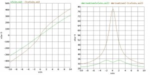
I hope you are feeling well. I'm taking a back seat on this stuff when, I guess, people are invested in a different way of looking at things. Anyway, here is a picture trying one more time to show what I am talking about. This is the simple voltage transfer funtion error of a simple CEF (Vin - Vout) for two bias levels and their derivatives. The distortion is related to the derivative once this output stage is put into a conventional op-amp configuration. The lower plot on the right is biased near the "Bernie Oliver" point where the translinear Vin vs Vout function becomes linear. In the first case there is considerable distortion without any switching necessary. Class "A" just keeps flattening this transfer funtion till the distortion matters less and less.
Where I come from crossover distortion has nothing to do with switching off of one side or the other of an output stage.
Attachments
Thanks Steve.
Some of these simulators are really expensive. I'm glad there's free SPICE simulation software available. Looks like Intusoft have a free demo version available that handles up to 20 components.
Back when I acquired mine, none of the free or cheap ones would model my circuit correctly. A couple simply showed no output signal at all. Fortunately for me, the company I was working for had three different SPICE programs I could choose from. I liked the Intusoft the best because at the time it had more features and a library of over 30K symbols. The head of engineering ask 3 of us working for him to take (legal and licensed) copies of all our software home so we could work from home at night and on weekends. They let me keep the software when I was laid off because they hired me back as a consultant.
Where I come from crossover distortion has nothing to do with switching off of one side or the other of an output stage.
Hi Scott,
I wasn't aware that that I had said anything to contradict that. I was a little more excitable a few months back and I could have said things without thinking them through. The doctors have cut my Prednisone back by 50mg a day so I am somewhat more civel now. I am sorry if I was harsh with you and some others here. Roid rage is real.
Member
Joined 2009
Paid Member
Hi Steve, I'm afraid I don't understand some of the posts above and haven't had luck simulating the Krill output myself - I use LTspice. My skills are improving slowly.
Anyhow, I was going to ask a different question, i.e. not one about whether devices are on or off, but, assuming that Krill works as you think, what next ?
Your amp has many people saying how nice it sounds. Is that the end ? Do you see ways in which this topology / biassing can be extended, perhaps to run at lower current through the driver stages, or built with non-BJTs ? simplifications for lower powers etc.
Just being curious...
Hi Steve, I'm afraid I don't understand some of the posts above and haven't had luck simulating the Krill output myself - I use LTspice. My skills are improving slowly.
I've posted the Krill LTspice simulation files in this post earlier in the thread. Ostripper contributed a lot to that (actually most of it), and I forgot to thank him earlier. Thanks OS! Just unzip it to a directory and run it. All you need to do is probe on the nodes you're interested in. It's ready to run and completely self-contained.
Steve hasn't posted his simulation files yet though.
your welcome... but I must really thank you ,Andy... for all the preliminary LT "coaching". Not only can I make any DIY amp work with any device (and sound good) , but I am making $$ using LT to dissect commercial amps.Thanks OS!
BTW - Steve .. cool website .. I like the 200 watter
!!OS
Steve hasn't posted his simulation files yet though.[/QUOTE
I took a day off. I zipped the file since .cir isn't one of the approved file types.
Attachments
Hi Steve, I'm afraid I don't understand some of the posts above and haven't had luck simulating the Krill output myself - I use LTspice. My skills are improving slowly.
Anyhow, I was going to ask a different question, i.e. not one about whether devices are on or off, but, assuming that Krill works as you think, what next ?
Your amp has many people saying how nice it sounds. Is that the end ? Do you see ways in which this topology / biassing can be extended, perhaps to run at lower current through the driver stages, or built with non-BJTs ? simplifications for lower powers etc.
Just being curious...
A lot of people have had trouble simulating the Krill, including me at first. Many of the earlier spice programs gave no results at all, god or bad.
Whether the Krill works as I think it does or not, it does work. I went in several directions with this circuit including high powered pro amps. I made several improvements to the schematics that improved performance also. My original goal was to build a very affordable and pleasant sounding amp. I also made high end amps because the demand was there. I had planned to show how this evolved over time, but it seems it became mired in controversy so I gave up. If the circuit works as I think, non BJTs would not bee a good choice due to their very low gate currents.
The circuit can be run at lower currents, but will switch before it reaches rated output. It still sounds good in my opinion. As for simpler, it would be difficult to make it any simpler than what I presented first. That schematic is on my web site.
- Status
- This old topic is closed. If you want to reopen this topic, contact a moderator using the "Report Post" button.
- Home
- Amplifiers
- Solid State
- Krill - The Next Generation