yeah but...
...(ignoring physics) the current from the +ve rail flows through all the output transistors to the -ve rail, under idle conditions there is no (perhaps very little) ground current...
so yes the 1.9A is for one rail, but at the same time it is both rails...
HTH
Stuart
...(ignoring physics) the current from the +ve rail flows through all the output transistors to the -ve rail, under idle conditions there is no (perhaps very little) ground current...
so yes the 1.9A is for one rail, but at the same time it is both rails...
HTH
Stuart
Well, it will probably take a week or so before I even want to see the amp so I'll get back to you when I start to check it.How's it going k?
Bit of an update...
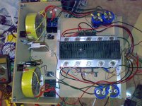
So now that i've (finally, after well over a year!!) got to 'finishing' the amp.... here's an update:
The box in the middle left is a 12v switchmode PSU for the fans and the relays. Both toroids are always plugged into the mains, but the 12v circuit switches relays (20amp 240v) which turn on the toroids. It is setup this way as my current amp has a low current 240v outlet that switches on when the preamp does, which is perfect!! I'm going to have a regulated circuit (it's tiny) to run the fans, i've got to put that in still (and build it), but it will allow me to switch voltages as I please (it'll be mostly set and forget hopefully!)... I'm now on the prowl for quieter fans, as the current ones are panaflow and they are fairly noisy IMHO! The timber will be changed to alloy once 'templates' are made") The side panels will likely be timber...
The side panels will likely be timber...
Aaron
So now that i've (finally, after well over a year!!) got to 'finishing' the amp.... here's an update:
The box in the middle left is a 12v switchmode PSU for the fans and the relays. Both toroids are always plugged into the mains, but the 12v circuit switches relays (20amp 240v) which turn on the toroids. It is setup this way as my current amp has a low current 240v outlet that switches on when the preamp does, which is perfect!! I'm going to have a regulated circuit (it's tiny) to run the fans, i've got to put that in still (and build it), but it will allow me to switch voltages as I please (it'll be mostly set and forget hopefully!)... I'm now on the prowl for quieter fans, as the current ones are panaflow and they are fairly noisy IMHO! The timber will be changed to alloy once 'templates' are made
The side panels will likely be timber...Aaron
Attachments
Just be careful since quiter often means less airflow. I bought a virtualy noiceless fan and it manages to keep one channel below 60 degrees celcius for about 2min.I'm now on the prowl for quieter fans,

Now I'm trying to decide if I am to use a 230V papstfan I bought from Steve at Apexjr instead or buy a more efficient 12V one and still use the fancontroll.
BTW
When measuring the temperature, I placed the sensor on the aluminium-mounting-thingie right next to one of the outputtransistors. This should get me a reading close to the temp of the transistors.
Print out a schematic, and go through every single resistor and cap, checking values. As each one is done, mark it with a permanant marker or dab of correction fluid.
Once that's all checked, then pull all the trannies and test them. At this stage you can test without the output boards connected, and the bias turned right down and I recommend you do so. The Krell behaves perfectly like this, and it avoids damaging expensive output devices.
Resistors checked (and measured) and all is as it should.
Caps are mounted the right way and at the right place.
Diodes are checked and working according to the meter.
The transistors are mounted in the right place and the right way according to the markings on the boards.
Guess that I'll have to desolder them next.
Hi Kmj,
have you accidentally swapped PNP for NPN?
No, that's the first thing I checked.
Q101, 103, 106 = MPSA42 (TO92)
Q102, 104, 105 = MPSA92 (TO92)
Q107 = MJE15033 (TO220)
Q108 = MJE15032 (TO220)
Q109 = MJE15032 (TO220)
Q110 = MJE15033 (TO220)
Q111 = MJE15032 (TO220)
On the output:
MJ15003 are connected to positive railvoltage, MJ15004 to the negative.
All Re connected together and to the positive speakerpost and to FB on driverboard.
D+ on driverboard connected to base on MJE15003 (well, to the resistor and then to the base.)
D- on driverboard connected to base on MJE15004 (same as on MJE15003)
EDIT:
Pinkmouse's BOM attached
Attachments
Hi Kmj,
To3s did you swap emitter and base?
Not what I can see. I'll describe it to be sure.
When looking at the MJ15003 from above and reading the typing in the correct way, then the base is to the right and emitter to the left. The oposite of that in the datasheet since the sheet shows the view from below.
Same thing on the MJ15004 (as discussed earlier).
Edit: Datasheet for ONSemi MJ15003 and 4 attached
Attachments
Hi Kmj,
that is not good enough.
The printing can be either way around, or anything in between.
Look at your hard wired connections, the pin side.
The pins are closer to one mounting hole than the other.
Call the closer hole the top, the pins are now in the upper half.
The base is on the left. Does your installation agree?
Most manufacturers show the pin side for their semis.
The only time we tend to look at the top side is when mounting in a PCB, but that does not apply to To3s, one NEVER sees the top side when wiring up. You always look at the pin side.
Look at your hard wired connections, the pin side.
The pins are closer to one mounting hole than the other.
Call the closer hole the top, the pins are now in the upper half.
The base is on the left. Does your installation agree?
Yes, that is the way I did the connections.
EDIT:
Most manufacturers show the pin side for their semis.
The only time we tend to look at the top side is when mounting in a PCB, but that does not apply to To3s, one NEVER sees the top side when wiring up. You always look at the pin side.
Ok, Noted
Hi Kmj,
Are you referring to the Thiel network on the output?
You need a minimum of the Zobel to give the amp a load at high frequency. i.e. the series R+C. but better to provide the whole network.
This can be mounted across the speaker terminals or on the output board, but here you need to run a line to audio ground.
I mean that there's nothing in between the emitterresistors and the speakerpost exept wire.Hi Kmj,
Are you referring to the Thiel network on the output?
You need a minimum of the Zobel to give the amp a load at high frequency. i.e. the series R+C. but better to provide the whole network.
This can be mounted across the speaker terminals or on the output board, but here you need to run a line to audio ground.
So I should add the Zobel and the combination of L201&R206 as well as the diodes between the different rails and speakeroutput (D201&202) and then draw a wire from the negative speakerpost to audioground on the motherboard?
My friends amp works great without these but if they could be causing the problem then I guess that I will have to add them. Any special values one have to use on the components, Watt on the resistors and what about the inductor?
Hi,
how has everyone else done the Zobel or Thiel on their KSA50s
Resistors need to be 4r to 10r and >3W. Most tend to adopt 10r, 5W. Carbon composition are often used.
Cap can be between 100nF and 180nF, again most go for 100nF, 100V and low inductance.
Inductor can be 1uF to 5uF. some will wind 15 to 30 turns of 1mm diameter enalled copper wire around the body of a large 10r resistor.
I wind 12turns in three layers (4turns per layer) of 1.4mm wire around an air core (temporary bobbin) 11 to 12mm in diameter.
I don't know, the only other amp I've seen in person is the one Jonas did (the friend) and the only difference in barts between ours are tha he uses one 1KVA 2x30V transformer and one rectifierbridge while I use 2pc of 550VA 2x27V transformers and two bridges.Hi,
how has everyone else done the Zobel or Thiel on their KSA50s
Not that this had anything with the network to do but I'm kind of stuck on the thought "we have the same source of parts and his amp works, why not mine?"
Well, I'll desolder the transistors this week and check them as well just to be sure. They did work when I measured them last week thou.
I have an LC-meter and copperwire so an iductor should pose no problem, some resistors shouldn't be so hard to find either but the closest I came to find in my usable-stuff-boxes was 10W MOX 2R2 resistors.
I wouldn't worry about the Zobel for now. The amp runs fine without it on the test bench, and at this point, is merely a distraction.
Ok, I'll save those things after the Re's to later.
Now I'm of for some decadent behavior, see (can one say/write "see" on a forum?) you all tomorrow, bright and early

Happy new year everyone (local time 19:07)
Happy New Year to all !!!
And a question:
I build 3 clones for now but never did eny experiments with feedback resistors. I allways used 12k1 and 475r.
What about 22k1 and 810r?
If this was descased in the past just point me there, this thread is extrimely loooong (which I'm happy for).
Thanks
Chicco
All The Best !!!
And a question:
I build 3 clones for now but never did eny experiments with feedback resistors. I allways used 12k1 and 475r.
What about 22k1 and 810r?
If this was descased in the past just point me there, this thread is extrimely loooong (which I'm happy for).
Thanks
Chicco
All The Best !!!
- Home
- Amplifiers
- Solid State
- Krell KSA 50 PCB