more, more, more...
From the diy perspective it's hard to argue against any of the changes you propose. None are strictly necessary, heck for a 50w/8ohm amp none are even remotely necessary, but then we are talking about a class A amp..."need" doesn't really apply...this is the audio equivalent of a hotrod...
Not sure what the peak output power would be, someone else will doubtless run the numbers. The 400VA transformer per channel is plenty, you can probably tweak the idle current up a bit (from the 1.9A default) if you measure the transformer and heatsink temp as you go.
The pinkmouse boards will happily drive the extra outputs, and using a little less idle current on each of a few more output transistors should have a few benefits:
1) spread the power over the heatsinks better
2) make each transistor a little cooler
3) give more margin for 'accidents' and welding...
4) lower intrinsic output impedance
5) ...
Additionally you may get benefits from the transistors operating in a more linear region of their transfer curve...
Of course you get to drill a lot more holes, in the right places...
Stuart
I don't want to regret the build effort later on with, "what If I did this and what if I did that".
Thats a classic statement that any builder of anything ALWAYS says after the fact! In reality you'd find that any pro amp designer would have ALWAYS done something differently the next time around. In nearly 30 years of building DIY amps I always found something I'd have done differently and thats part of what makes DIY so much more interesting and better than buying a production unit. In actuality we CAN go back and make major changes if we want to but an amp designer with a thousand amps in production can only make very minor mods after the fact.
Build on... we can't bear to Wait any longer
") .
.Mark
Re: more, more, more...
50 Watts! What's all the fuss about? "Build on"...good words. Perhaps it is "gasser" size as a hot rod?
I picked up some more etching solution. I hope the aluminum is ready for pick up tomorrow? The supplier may be putting me off due to the holidays and such? 
Cheers,
Shawn.
Stuart Easson said:...this is the audio equivalent of a hotrod...
Mark A. Gulbrandsen said:Thats a classic statement that any builder of anything ALWAYS says after the fact!
Build on... we can't bear to Wait any longer
50 Watts! What's all the fuss about?
"Build on"...good words. Perhaps it is "gasser" size as a hot rod? I picked up some more etching solution.
I hope the aluminum is ready for pick up tomorrow? The supplier may be putting me off due to the holidays and such? Cheers,
Shawn.
Attachments
Re: Re: more, more, more...
Shawn,
it's not about top fuel or funny cars.
Are you familiar with the Pike's Peak hill race in Colorado ?
Most amplifier designs are voltage amps, the ideal voltage amplifier delivers a constant voltage in any load impedance.
I've only seen a few designs that get as close as within a few percent to perfection in the 2 to 8 ohms range.
Ideal voltage amps do not exist and the ones that get close cost mucho hardware, so most designers skip the prime directive and aim for the target of minimal distortion.
The good ones still reach for getting 90% right at a 4 ohm load impedance level, which can still be called economical and obtained without excessive hardware.(see Bob Cordell)
If distortion is the main theme, why not skip the high dissipation levels alltogether, move straight to class AB and tweak with the settings to get minimal crossover distortion.
That way you don't need the big heatsinks and the big transformer, the big capacitors go out the window too, you might as well reduce the output devices max. power number by two thirds.
The result: you end up driving on a flat highway in a 40mpg Toyota, audio amplifier history in a nutshell.
Someone like Stuart isn't driving on the highway, he lives on Duetta hill. The Toyota would go down the hill ok, but going up again he'd break down at the first hole on the ascent.
You can build a class AB amp that can drive up that hill, but it will start to look like a class A 50 watter.
A Halo JC1 is something like that, hotrodding that amp with turbocharged megacooling and even more hardware can make it do the same 400 watts power rating in full class A.
Sort off like a performance and blueprinting job on a regular pushrod high displacement US car engine.
Combined with a high performance and generally more difficult loudspeaker, most of the "standard" 50 watts class AB amplifiers would actually be less than a 25 watts amp in ideal voltage amplifier terms.
With exception of a few highlights, the average British made amplifier was/(is) even far worse.
Which is somewhat awkward considering the slopy but excellent British loudspeaker landscape.
Class A is not just about cancelling crossover distortion, it also has to do with reaching for the ideal constant torque audio engine.
A lot of people find it amusing to ridicule the simplicity of the KSA design, just like gas guzzler US automobiles used to be ridiculed in the past. Guess what : nowadays the top class car scene is all about supercharger technology, auto shifters and all-wheel drive. And they've long forgotten they used to ridicule cruise control, power windows, and 14 McD. size cupholders in a vehicle. Even worse: the no1 status item in the place i live at and the rest of the globe is a humvee H2 !
With high performance active parts, separate and regulated rails, a beefed-up HD powersupply, a PROPERLY layed out DC-servo, and a mega output stage for the wild ones, the KSA is capable of even more.
(stuff i've posted so many times on this thread that this is the closing act)
Ask yourself why Mark has been building amps for 30 years, including Passlabs gear, and yet likes the KSA so much. Maybe because he lives close to the Rocky Mountains ?
TomWaits said:50 Watts! What's all the fuss about?
Shawn,
it's not about top fuel or funny cars.
Are you familiar with the Pike's Peak hill race in Colorado ?
Most amplifier designs are voltage amps, the ideal voltage amplifier delivers a constant voltage in any load impedance.
I've only seen a few designs that get as close as within a few percent to perfection in the 2 to 8 ohms range.
Ideal voltage amps do not exist and the ones that get close cost mucho hardware, so most designers skip the prime directive and aim for the target of minimal distortion.
The good ones still reach for getting 90% right at a 4 ohm load impedance level, which can still be called economical and obtained without excessive hardware.(see Bob Cordell)
If distortion is the main theme, why not skip the high dissipation levels alltogether, move straight to class AB and tweak with the settings to get minimal crossover distortion.
That way you don't need the big heatsinks and the big transformer, the big capacitors go out the window too, you might as well reduce the output devices max. power number by two thirds.
The result: you end up driving on a flat highway in a 40mpg Toyota, audio amplifier history in a nutshell.
Someone like Stuart isn't driving on the highway, he lives on Duetta hill. The Toyota would go down the hill ok, but going up again he'd break down at the first hole on the ascent.
You can build a class AB amp that can drive up that hill, but it will start to look like a class A 50 watter.
A Halo JC1 is something like that, hotrodding that amp with turbocharged megacooling and even more hardware can make it do the same 400 watts power rating in full class A.
Sort off like a performance and blueprinting job on a regular pushrod high displacement US car engine.
Combined with a high performance and generally more difficult loudspeaker, most of the "standard" 50 watts class AB amplifiers would actually be less than a 25 watts amp in ideal voltage amplifier terms.
With exception of a few highlights, the average British made amplifier was/(is) even far worse.
Which is somewhat awkward considering the slopy but excellent British loudspeaker landscape.
Class A is not just about cancelling crossover distortion, it also has to do with reaching for the ideal constant torque audio engine.
A lot of people find it amusing to ridicule the simplicity of the KSA design, just like gas guzzler US automobiles used to be ridiculed in the past. Guess what : nowadays the top class car scene is all about supercharger technology, auto shifters and all-wheel drive. And they've long forgotten they used to ridicule cruise control, power windows, and 14 McD. size cupholders in a vehicle. Even worse: the no1 status item in the place i live at and the rest of the globe is a humvee H2 !
With high performance active parts, separate and regulated rails, a beefed-up HD powersupply, a PROPERLY layed out DC-servo, and a mega output stage for the wild ones, the KSA is capable of even more.
(stuff i've posted so many times on this thread that this is the closing act)
Ask yourself why Mark has been building amps for 30 years, including Passlabs gear, and yet likes the KSA so much. Maybe because he lives close to the Rocky Mountains ?
Re: Re: Re: more, more, more...
Jacco, not to give you a big head, but you should be columnist. Your knowledge in diverse areas, including audio added with a touch of humor is really refreshing!
jacco vermeulen said:
Shawn,
it's not about top fuel or funny cars.
Are you familiar with the Pike's Peak hill race in Colorado ?
Most amplifier designs a..... edited..... likes the KSA so much. Maybe because he lives close to the Rocky Mountains ?
Jacco, not to give you a big head, but you should be columnist. Your knowledge in diverse areas, including audio added with a touch of humor is really refreshing!
K-amps said:big head
Yeah,
the Rocky Mountains was a good flash, wasn't it.
Let's hope Mark is not into opera only.
(most don't seem to get my red nose routine though, got a reprimand on the exile forum again this week)
Th, K.
Re: Re: Re: more, more, more...
Mister metaphor! Wow! Can I interpret: You like the original design and see no flaw in it? You like V regulation very much and if it was up to you the Driver PCB would be supplied by regulated rails? No need to install x2 1000VA toroids and no need to install a couple hundred thousand u of capacitance? And you are a car fanatic? It all sounds good to me.
I have low profile extrusions to build the chassis from so it is getting too tight for me in my original layout. So I will add the fourth set to increase the depth of the cabinet, hence I will install 8 outputs per channel (4x NPN & 4x PNP) and this will place only two devices per heat sink. Just because the aluminum is there and why not? The metal supplier came through and I have most of the aluminum to bolt it together. The next part will be the hardest as I do not have a metal working shop but I'm up to the challenge. If I muck it up I can use Mark's classic take and say what if... I'm certain there will be some what if's anyway. The man has a point.
I know jack about Pike's Peak but it sure looks impressive on the net in pic's. I actually skipped out on two training courses a few years back and they were held at...
My Jacco Vermeulen decoder pen ran out of ink so if I have misunderstood the colorful metaphors, then let me know.
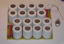
Liberace dropped in at my place while I was soldering the capacitor banks together. He said, "Here son, use my caps. They are better looking." I swear it's the truth.
Albino caps? What's next? Who knows?
Thanks to all & Happy Holidays if you have any,
Shawn.
jacco vermeulen said:Shawn,
it's not about top fuel or funny cars.
Are you familiar with the Pike's Peak hill race in Colorado ?...
Mister metaphor! Wow!
Can I interpret: You like the original design and see no flaw in it? You like V regulation very much and if it was up to you the Driver PCB would be supplied by regulated rails? No need to install x2 1000VA toroids and no need to install a couple hundred thousand u of capacitance? And you are a car fanatic? It all sounds good to me. I have low profile extrusions to build the chassis from so it is getting too tight for me in my original layout. So I will add the fourth set to increase the depth of the cabinet, hence I will install 8 outputs per channel (4x NPN & 4x PNP) and this will place only two devices per heat sink. Just because the aluminum is there and why not? The metal supplier came through and I have most of the aluminum to bolt it together. The next part will be the hardest as I do not have a metal working shop but I'm up to the challenge. If I muck it up I can use Mark's classic take and say what if... I'm certain there will be some what if's anyway. The man has a point.
I know jack about Pike's Peak but it sure looks impressive on the net in pic's. I actually skipped out on two training courses a few years back and they were held at...
My Jacco Vermeulen decoder pen ran out of ink so if I have misunderstood the colorful metaphors, then let me know.
Liberace dropped in at my place while I was soldering the capacitor banks together. He said, "Here son, use my caps. They are better looking." I swear it's the truth.
Albino caps? What's next? Who knows?
Thanks to all & Happy Holidays if you have any,
Shawn.
Attachments
Re: Re: Re: Re: more, more, more...
Jacco- I'll just swipe my hat and take a deep bow.........
Class-A amps. vs motoring??
Maybe the KSA and the likes are more like the supercharged bulldozers of audio? Something more like super constant torque instead of max horsepower at max rev's, much like the Toyota in your metaphor??
Well, it just turned december 24th... for scandinavians X-mas eve is THE day of X-mas, where it all happens.. I better get to bed before the " extra stout one with the red coat" sweeps my chimney!
I wish you all the very best for the season! May you all have a very merry X-mas!
K-amps said:
Jacco, not to give you a big head, but you should be columnist. Your knowledge in diverse areas, including audio added with a touch of humor is really refreshing!
Jacco- I'll just swipe my hat and take a deep bow.........
Class-A amps. vs motoring??
Maybe the KSA and the likes are more like the supercharged bulldozers of audio? Something more like super constant torque instead of max horsepower at max rev's, much like the Toyota in your metaphor??
Well, it just turned december 24th... for scandinavians X-mas eve is THE day of X-mas, where it all happens.. I better get to bed before the " extra stout one with the red coat" sweeps my chimney!
I wish you all the very best for the season! May you all have a very merry X-mas!
Torque *RPS = Power
V * I = Power
There is something like a universal truth.
On the quarrel tech threads overhere you can read that class AB amps can also benefit from traditional class A territory stuff, and that developments from the class AB world can improve a class A amplifier.
I constructed my first vertical mosfet power amplifier in 1987, converted the design to class A because i really did not like the class AB outcome. Mosfets were much more expensive than BJTs in those days, they've become very popular devices because you can now buy an IRFP240 for a buck the piece.
Now there are endless tech-head threads overhere on the optimal bias level for vertical mosfets.
What i like about the classic topology of the KSA is that it's easy to construct for a layman, and a great blueprinted short block for a performance tuning.
It's a breeze to double the horsepower on a Harley, to do the same on a 4-cylinder Kawasaki you'll need a lot more tools and a lot more expert knowledge.
Pavel Dudek's designs are high rev. Honda bikes.
Had he been living a thousand miles closer to the US, with my resources, he'd been one the 10 big guys.
You'll need a 50 page manual to build one of his amps, if you have the right parts, which you don't.
i know more about engines than audio, only been doing audio for 25 years. I've tweaked anything from lawnmowers to turbine and submarine engines, converted a BMW R600 for motorcrossing at 10. I can buy a Candy amp but where's the fun ? Rudy (the red nose) relic Diesel has been beating Nicky Otto for half a decade, check out the Audi 6ltr V12 Diesel.
http://media.audiusa.com/article_display.cfm?article_id=9800
Mister Metaphor sounds nice.
no.The Audi R10 TDI is unbeaten since making its debut at the 12 Hours of Sebring last March. The revolutionary diesel sportscar started eight races and took the checkered flag as winner on each occasion - impressive proof of the efficiency of Audi TDI Power
Impressive proof that the Authorities got the conversion wrong when attempting to make the new category attractive to entrants.
As was done in many other decades, when the conversion formula was wrong the Authorities just altered it or removed the option to make the normally aspirated petrol engine reign (apparently) supreme
Hello I am watching this krell remote factories
Nice work folks.
I have question when using Toshibas 2sc5200 2sa1943 are there changes required to the components values? They have higher frequency gain 10mhz so there might be some problems implementing them as they are.
Anyone build this version please share the notices.
Nice work folks.
I have question when using Toshibas 2sc5200 2sa1943 are there changes required to the components values? They have higher frequency gain 10mhz so there might be some problems implementing them as they are.
Anyone build this version please share the notices.
Chassis
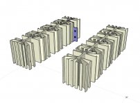
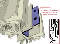
I have 4 extrusions for each side on the amp I'm building. I did up an image in Sketch-Up of the lay out. I'm planning to place 1/4 inch thick angle aluminum flying off each heat sink. This will allow me to place the TO-3's in a single profile on the inside of the chassis. I was planning to cut the extended aluminum lower at the top of each portion and run a "bus" across the top of each side of the amp.
My reasoning is if I place the TO-3's deep inside each heat sink as they exist, I will end up with alot of wire and a difficult amplifier to MOD and/or service. If I use the aluminum extentions, life is better and easier?
This is the best I could come up with and I was wondering if any folks could see it a better way.
Regardless, I'm going to try it out over the next day or so but if someone had a better idea, I'd like to hear about it.
Cheers,
Shawn.
Attachments
Hi Tom.
the To3s get placed directly on the flat middle section of each sink. No angle is required and adding that angle WILL make the transistors run hotter. Don't!!!!
The To3 can sits on the outside and the pins face in towards the PCBs. hard wire them together. someone posted a pic showing the emitter resistors hard wired into the space between the fins next to the pins.It all looked quite neat.
I got some of those mounted on the heatsink I bought and I can only say that if you can get ahold of some, then DO! They are a delight to work with.If ease of install is desired, TO-3 sockets is an option
- Home
- Amplifiers
- Solid State
- Krell KSA 50 PCB