Fellow Clone builders
I am told by a "connaisseur" that, for those who are looking for TO-264 output devices, the 2SC5200 and 2SA1943 from Toshiba are a very good combo. I was also told (the same guy) that for this type of amp, matching of the output devices would bring a great benefit to the final result.
Any comments, anyone?
Regards
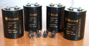
GeWa said:These baby's arived today! Four Kendeil power caps and Elna Silmic capacitors for C102 & C103.
Regards
Those Kendeil look awsome. How much did you pay for those? Where to get them?
transistor matching...
Don't want to tread on anyones toes, so don't consider this as a statement of the 'quality' of the sound the amp puts out more a comment on the electronic engineering aspect of transistor matching...
From a current sharing perspective, if the value of the output stage emitter resistors are 'large', ie 0r5 and up, the accuracy of output transistor match becomes much less relevant, the larger the value the closer the sharing will be. For 12 device pairs I plan on using an ohm or more, probably 2 of the 0r68 resistors in series.
Ultimately other things will introduce more variability than the transistors...
For example, on the heatsinks I am using, for the first couple of hours of operation, the temp. difference between a transistor on the end vs one in the middle is large enough to induce a bigger Vbe change than was intrinsic to the transistors to begin with. If one were really interested in 'true' matching of output devices there would need to be a way of doing it in situ with the emitter resistors included, at the typical temp. etc...and of course you'd need to start with a big bunch of transistors that didn't match in convenient amounts...
I'm not saying it's pointless to match output transistors, but make sure you understand what your goals are, and how to tell if you've achieved them...
I'd hypothesise that matching the halves of the diff. pairs in the front tend would give better results, measured and sonically, plus of course you might find the output offset drops...
Stuart
GeWa said:matching of the output devices would bring a great benefit to the final result.
Matching total pnp and npn Hfe :yes.
matching the ones in parallel: Stuart's rule.
To apassgear
They're 31€ a piece. I got them from De Audio Fabriek in Holland. I don't know if there's a dealer in your part of the world. It's not the cheapest cap around but certainly not the most expensive either.
Regards
They're 31€ a piece. I got them from De Audio Fabriek in Holland. I don't know if there's a dealer in your part of the world. It's not the cheapest cap around but certainly not the most expensive either.
Regards
When you guys are listening to your already built KSA50, I'm still working on some peripheric circuits. I collected differents circuits and put together a nice little circuit that combined soft start and standby functions. I'm planing to build a PCB that contain both.
The circuit is turn on by a main AC switch, possibly on the back of the amp then the softstart activate. The softstart is the Elliot Project 39 version. A nice feature is that a small rating external switch can be used to turn on/off the amp from the front, it connects instead of a jumper on JP1.
Two nice additions are a safety feature of the soft start, a thermal cut off fuse, that will be mounted between the power resistors. It prevents any catastrophic failure. The circuit can also power two 12Vdc fans. Their speed can be reduced by adjusting the value of R10.
Then working on the same 24V supply is the standby circuit. It is operated from a front mounted switch/led assembly or by remote 12V trig on the back. It provides these features:
-Auto-reset at start-up, standby mode activated, led inside power-on switch is flashing.
-Two DPDT relays can be used to provide the standby functions. I'm planning to short the inputs and select the lowest channel's bias setting in standby. The JP1 jumper can select the relays state in standby, On or Off.
-Press the SW1 switch, and the amp turn On full bias and ready. The SW1 led turn on continuously. The momentary switch is well debounced and don't produce any false trigger.
-A 12V remote trigger on the back can activate the power-on mode remotly.
I'll use the same desing on a pair of Aleph X monoblock that I build one day
I don't pretend it is a perfect desing. It uses some parts I already have in stock and it is working perfectly. That is enough for me
Attachments
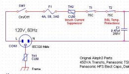
The over-temperature cut off will be implemented using thermostat directly mounted on each channel heatsink, in serie with the main power switch and fuse, just before the soft start PCB. See this extract of my Aleph30 schematic showing their connection.
The digikey part number for the cut off is: 317-1085-ND
Thermostat, 75 DegC, Normally-Closed
The digikey part number for the cut off is: 317-1085-ND
Thermostat, 75 DegC, Normally-Closed
Attachments
I just thought of an other usefull option. In case that we use a protection circuit inside the amp, to open the speaker terminal for example, an Alarm option will be available on the standby board.
In Power-On mode (steady On led), a 12V alarm relay voltage will activate a rapidly flashing led. The relay desing insure that even if the protection circuit is floating on some other voltage, it can still interface easily with the standby pcb. Just a thought
In Power-On mode (steady On led), a 12V alarm relay voltage will activate a rapidly flashing led. The relay desing insure that even if the protection circuit is floating on some other voltage, it can still interface easily with the standby pcb. Just a thought
Attachments
It is not all over the place. The thermostats are mounted on the back of the heatsinks, close to the back of the amp where the AC gets in.
Most commercial amps, including PassLabs are protected this way. It is the most reliable way, to cut the main power, to protect the amp in case of over temp.
But I agree, it needs to be well put together. Main AC voltage are dangerous
Bye...
Most commercial amps, including PassLabs are protected this way. It is the most reliable way, to cut the main power, to protect the amp in case of over temp.
But I agree, it needs to be well put together. Main AC voltage are dangerous
Bye...
- Home
- Amplifiers
- Solid State
- Krell KSA 50 PCB