Nico Ras said:
I SHOULD BE SHOT FOR GENERALIZING
Had a look, you are absolutely right. Wonder if they changed designers with this particular project.
naah ..... your good intention is what's count .......
")
we can make them both ways , that's the point .
as I understand it - gnd is important only for speaker itself ; for electronic it's just a reference , not ( hopefully not) energy path .
I'm soon ready building my input board.
Next thing is to try them, before building rest of the amp.
Is there any information/guide how to try them without breaking them.
How do I set Bias and DC ( VR 1 / VR 2 )
Could I start with lower +VCC
Then attach Tone Generator to Input, and use an oscilloscope to
look at the signals.
Is there any good Testpoints, Values etc..
Do I need to have some resistors at Output ?
Sorry for all those "stupid" questions, but this is my first amp project
I think PWatts has given some information that stated the LTP and driver stage could be tested without the power stage connected. But Im not sure of the schematic network he suggested because I couldnt find the actual posts in this thread so you/we have to ask him again.
Fix, You could start with a low rail voltage but for a proper test with generator you need at least ±42-44V for the LTP (zeners are 39V so rail voltage must be higher than that).
Fix, You could start with a low rail voltage but for a proper test with generator you need at least ±42-44V for the LTP (zeners are 39V so rail voltage must be higher than that).
if you want to drive 1 to 2ohm loads then stick with the MJE series.umut1001 said:is there any alternative transistor for mje15030 and 15031 ? because its hard to match them..hfe are very far eachother..thanks
15030/1, or 15032/3, or maybe best of all 15034/5.
If a severe 4ohm load is as bad as you are ever going to drive, then you can try using 2sb649/d669 as drivers.
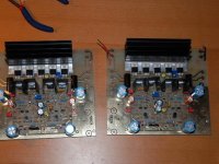
There is life...
Havn't tried it at 42v, just at 25v ( 35v for short time)
One card is working as it should, the other I place a transistor wrong, will change it tomorrow.
Now I need to knew where to measure so I can build the rest, but it looks promising.
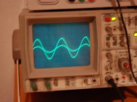
Input signal and output signal..sd
Havn't tried it at 42v, just at 25v ( 35v for short time)
One card is working as it should, the other I place a transistor wrong, will change it tomorrow.
Now I need to knew where to measure so I can build the rest, but it looks promising.
Input signal and output signal..sd
Attachments
Been a while since I last checked.. Fix, how's your amp coming along, or for that matter anyone else's?
The feedback loop is complete without the output stage so it can be tested as-is. In fact, some distortion measurements I made with the boards alone were _extremely_ good so it can be used as a damn good headphone amp if the gain is dropped.
IIRC I got the amp to work with fairly low rails, it doesn't have to be >39V. The performance will naturally just not be too hot but it should still play low-amplitude audio. If it does and there's low&symmetrical current draw from the supplies you can move on to the big rails.
Hi Pierre,
good to hear from you again. I have assembled all the boards including output boards I made for the 8 pairs of plastic transistors. I am having a hell of a time trying to fit these and four transformers in one enclosure. I am seriously considering putting the power supply into a seperate case. I hate metal work.
Regards
Harry
Work and other unimportant stuff been taking my time...
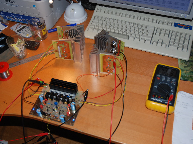
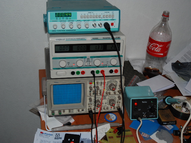
But I have worked hard and have actually made a test run on one channel.
Pictues and other stuff for my Krell Clone
I made a test, 31VDC, 400mv on Emitter Resistors, Circuit is drawing 1.8Amp
Since there is no smoke, and input signal is matching output signal ( yes output signal is amplified.. )
I guess I've managed to come this far.
Now the metalwork is starting...
Below is some pictures...
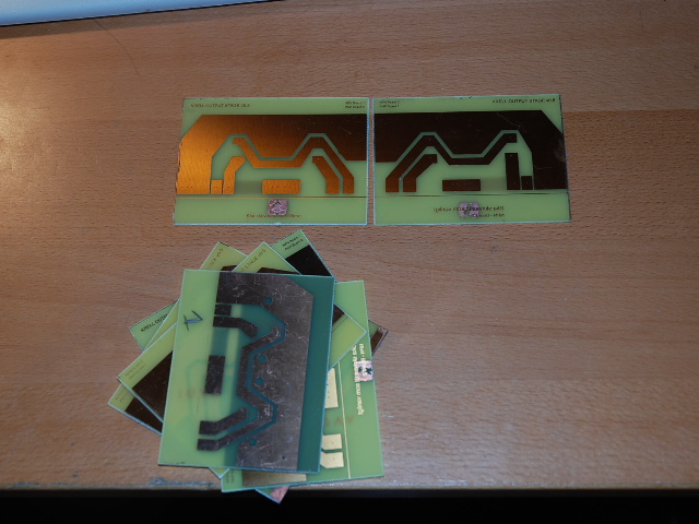
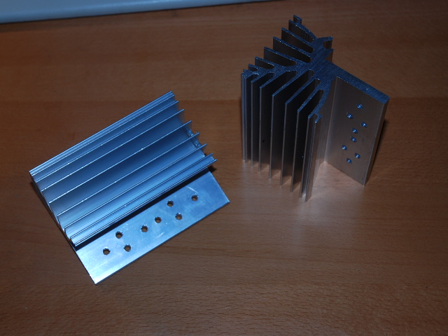
PCB for the heatsinks..
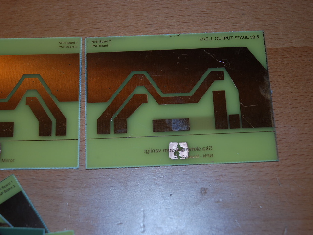
PCB for the heatsinks..
Heatsink is now Cut and Drilled
PCB test mounted on Heatsink, Emitter Resistors soldered.
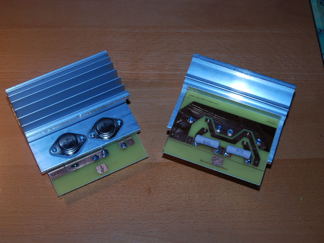
1 Channel, NPN & PNP side
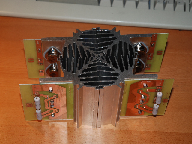
Other View...
Channel is now ready for testing.. Running at 31VDC and 120mv
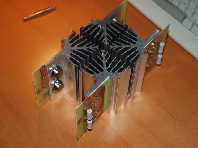
Channel up and running.. No smoke
But I have worked hard and have actually made a test run on one channel.
Pictues and other stuff for my Krell Clone
I made a test, 31VDC, 400mv on Emitter Resistors, Circuit is drawing 1.8Amp
Since there is no smoke, and input signal is matching output signal ( yes output signal is amplified.. )
I guess I've managed to come this far.
Now the metalwork is starting...
Below is some pictures...
PCB for the heatsinks..
PCB for the heatsinks..
Heatsink is now Cut and Drilled
PCB test mounted on Heatsink, Emitter Resistors soldered.
1 Channel, NPN & PNP side
Other View...
Channel is now ready for testing.. Running at 31VDC and 120mv
Channel up and running.. No smoke
Very nice! Keeping close to the original design. Hope you maintain the same closeness with a decent power supply too.
Important to keep the wiring to the output stage as short as possible, esp if using other transistors than the 1500x's.
Looking forward to some listening impressions - nobody's project that I know of has progressed that far yet..
Important to keep the wiring to the output stage as short as possible, esp if using other transistors than the 1500x's.
Looking forward to some listening impressions - nobody's project that I know of has progressed that far yet..
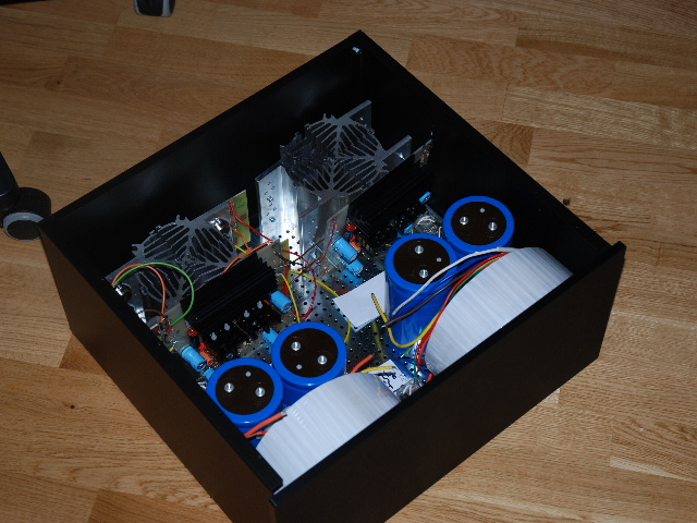
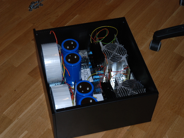
Just wanted to post some photos of my "setup"
Will fit in the Hifi 2000 Pesante Chassi.
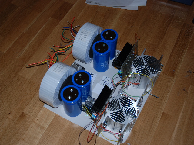
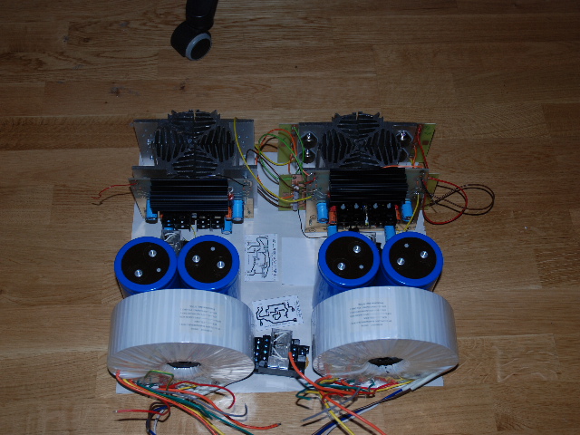
Hifi2000 - Chassi
Will fit in the Hifi 2000 Pesante Chassi.
Hifi2000 - Chassi
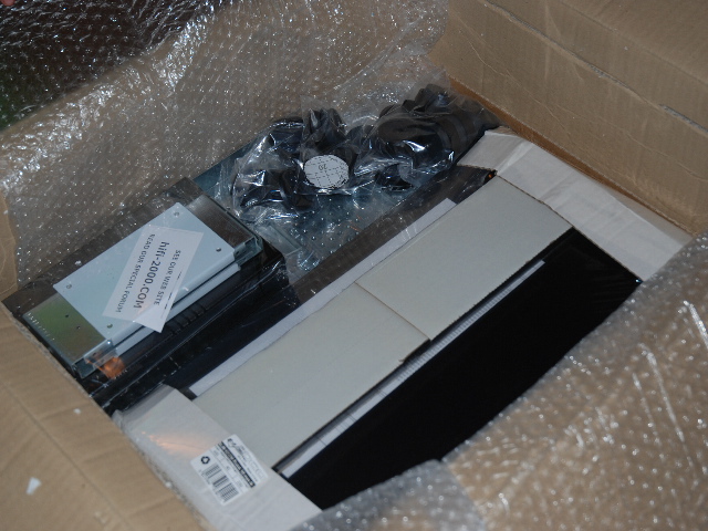
Got my Chassi today.
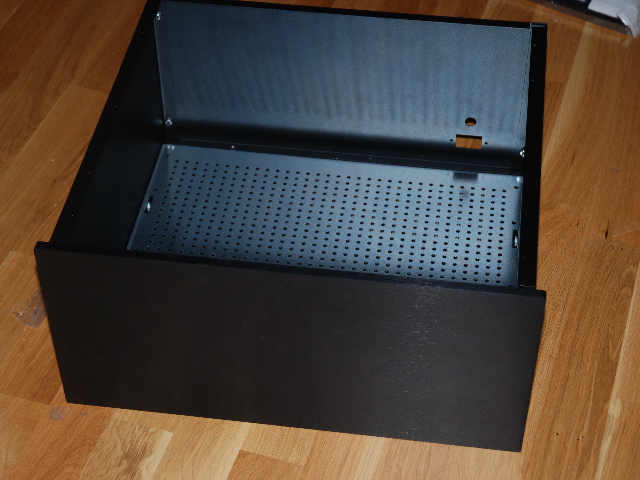
This looks real good, lots of space left.
Top is Vented for the fans.
Also bottom is vented.
Could be hard to see on pictures, and I'll modify it further.
Maybe I need to reinforce bottom, trafos is heavy.
Will post more pictures soon as I'm completed next task.
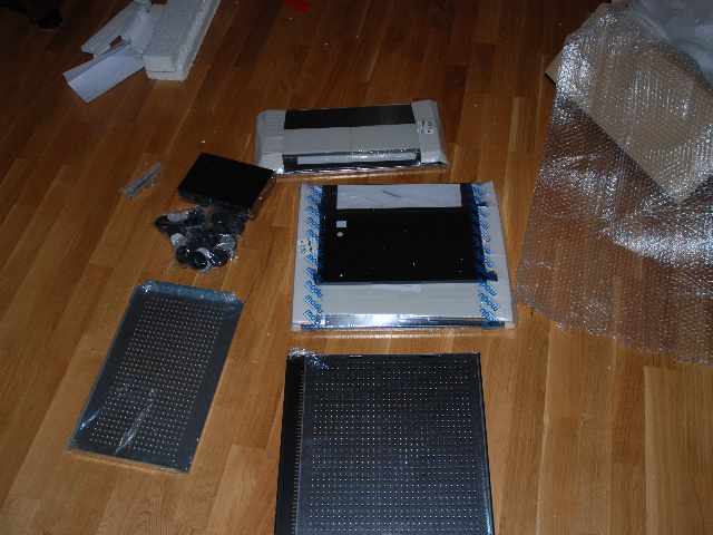
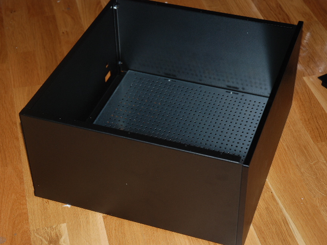
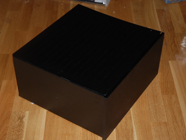
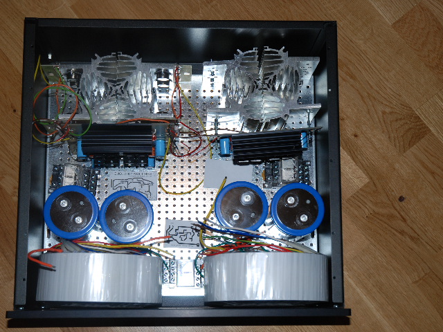
Time to build !
This looks real good, lots of space left.
Top is Vented for the fans.
Also bottom is vented.
Could be hard to see on pictures, and I'll modify it further.
Maybe I need to reinforce bottom, trafos is heavy.
Will post more pictures soon as I'm completed next task.
Time to build !
OK... more pictures...
hmm.. No comments on last since last post...
Some Aluminium, drillplate for fast drilling
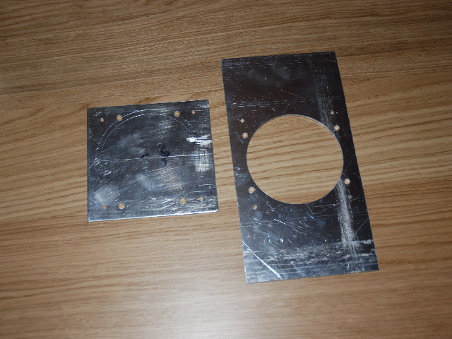
After some violence...
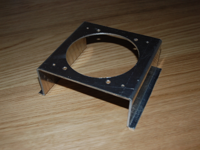
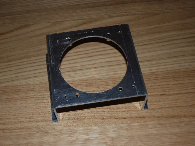
Fan is in place.. ( will buy new fans later ... )
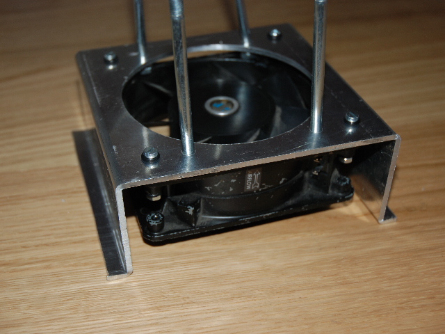
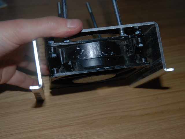
With Heatsinks... Yes bolts are to short...
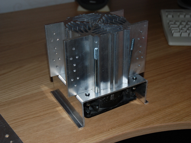
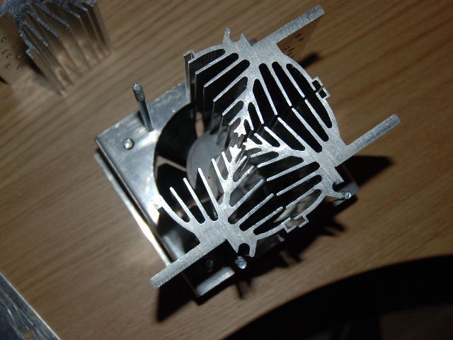
Moving forward... next week both cooling towers will be ready..
hmm.. No comments on last since last post...
Some Aluminium, drillplate for fast drilling
After some violence...
Fan is in place.. ( will buy new fans later ... )
With Heatsinks... Yes bolts are to short...
Moving forward... next week both cooling towers will be ready..
- Home
- Amplifiers
- Solid State
- Krell KSA 100mkII Clone