Originally posted by K-amps I got 2 identical trafo's of DIYaudio (some guy's Aleph project) and put them in a couple of Forte Model 3's. One hums up the system, the other does not when connected . The one that does, is off by 6vac gnd to gnd.
Hmmmm, doesnt sounds good. But there must be a reason for such a cheap transformer?


still4given said:
One of my KSA50's does that. By itself, no hum. Hooked up with any other amps I get a hum from all. What do I check for?
Thanks, Terry
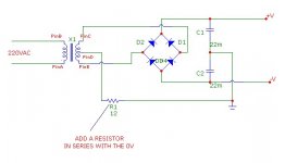
Do this, it works. There are other solutions as well this is simple and you can use values between 10 - 27 ohm 1/2 watt.
Attachments
Nico Ras said:
Do this, it works. There are other solutions as well this is simple and you can use values between 10 - 27 ohm 1/2 watt.
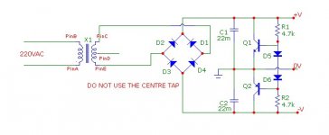
THIS IS EVEN BETTER.
Attachments
Nico Ras said:
Do this, it works. There are other solutions as well this is simple and you can use values between 10 - 27 ohm 1/2 watt.
Thanks, I'll try that. 1/2 watt is enough?
Blessings, Terry
It's to do with the PCB fabrication process, without the plating the board house would have to drill it out themselves which increases cost.
I looked at the schematic.
Do I need to drill everyhole, or just Q13 since Q14/16 and Q15/17 share gnd ?
Or do I need to drill at all and don't use bushings.
It looks that it just puts GND on screws.. ????
Nico Ras said:
Do this, it works. There are other solutions as well this is simple and you can use values between 10 - 27 ohm 1/2 watt.
How much current do you reckon flows at center Tap... I'd hate to blow the resistor and thus the whole amp... what am I missing? To me the center tap from the trafo is the anchor... if broken, the boat sails away for good...
I could perhaps think about this fix at the input gnd after all thats where it connects to the rest of the system... I would not open up the star ground...
THIS IS EVEN BETTER.
I thought a floating ground like you show was a no-no.
So you can make a dual rail PS from a single secondary, non centertapped tranny?
What are Q1/Q2, D5/D6? Wow...
What is the estimated output VDC (ie +/- 1.4*VAC)...
john65b said:
I thought a floating ground like you show was a no-no.
...
look for Quad 606 schematic
Zen Mod said:
look for Quad 606 schematic
Seems everything is floating referenced with 10R to the chassis and safety ground. I'd like to convert my 405 to do the same, but I'm worried about how much "float" I can expect... (And I'm also unsure what to do with the 405's internally split ground, in that case.)
P.S: I like the single fuse in the 606. Don't like the rail fuses in the 405, as I don't care one iota about the amp compared to my speakers.
Regards
still4given said:
Thanks, I'll try that. 1/2 watt is enough? 1/2 watt is fine. After you decide it is a great idea, try the next circuit.
Blessings, Terry
K-amps said:
How much current do you reckon flows at center Tap... I'd hate to blow the resistor and thus the whole amp... what am I missing? To me the center tap from the trafo is the anchor... if broken, the boat sails away for good...
I could perhaps think about this fix at the input gnd after all thats where it connects to the rest of the system... I would not open up the star ground...
There should zero current flowing in the transformer centre tap.
You don't have to open the ground star.
Patrik Floding said:
Seems everything is floating referenced with 10R to the chassis and safety ground. I'd like to convert my 405 to do the same, but I'm worried about how much "float" I can expect... (And I'm also unsure what to do with the 405's internally split ground, in that case.)
P.S: I like the single fuse in the 606. Don't like the rail fuses in the 405, as I don't care one iota about the amp compared to my speakers.
Regards
Because there is no reference to the 50 Hz of the transformer to the 50 Hz of other transformers in the system there is no 50 Hz/100Hz signal in the ground.
Terry is experiencing this in that one or several of the other equipment "zero volt" or ground is not quite zero volts. and the 50/100 Hz signal appears in the amplifier as hum.
All a.c. is flowing trough your capacitors which is not only the "reservoir" but also the low impedance path for the loudspeakers, while d.c. references V/2 and not zero volts.
Nico
Zen Mod said:
look for Quad 606 schematic
Hi Zen,
if I am not mistaken all transistor Quad amps uses this method, also quite a number of other "esoteric" types, those whose designers know what this circuit is.
The headphone amp guys use a complete amplifier to achieve this and only because they don't know
 what it is that they are implementing.
Nico
Nico Ras said:
Hi Zen,
if I am not mistaken all transistor Quad amps uses this method, also quite a number of other "esoteric" types, those whose designers know what this circuit is.
The headphone amp guys use a complete amplifier to achieve this and only because they don't know
Nico
I agree with most , except that - not all Quad amps use that technique;
405 , for instance , use plain vanilla center tap
today i took my multimeter and try the mje15030 and 15031..
15031has hfe of 170,295,273,174,279,272,345,390,165,200,295,264,178,155
and 15030 are
89,86,60,67,65,64,64,61,75,78,70,98,81
my friend said that he matched them by using multimeter..and he says there is 0mv offset when the trimpot is in the middle..what can i do for matching? these are too far for matching..
Zen Mod said:
I agree with most , except that - not all Quad amps use that technique;
405 , for instance , use plain vanilla center tap
I SHOULD BE SHOT FOR GENERALIZING

Had a look, you are absolutely right. Wonder if they changed designers with this particular project.
umut1001 said:today i took my multimeter and try the mje15030 and 15031..
15031has hfe of 170,295,273,174,279,272,345,390,165,200,295,264,178,155
and 15030 are
89,86,60,67,65,64,64,61,75,78,70,98,81
my friend said that he matched them by using multimeter..and he says there is 0mv offset when the trimpot is in the middle..what can i do for matching? these are too far for matching..
Multimeter matching assumes all transistors are small signal. Try matching using the expected currents with an external test.
Set a constant current generator for bias and then find close matches in collector current.
- Home
- Amplifiers
- Solid State
- Krell KSA 100mkII Clone