For the moment I will use DIYCable 1000VA trafo.
When the amp is ready and working I'll decide what to do.
The DiyCable trafo has all needed voltages and could be good enough...
- - -
Update:
Mounted the trafos at last, pictures will come..
AMP is now 33.5KG and guess it will be 35-40KG when done.
Just for a 100W amp")
When the amp is ready and working I'll decide what to do.
The DiyCable trafo has all needed voltages and could be good enough...
- - -
Update:
Mounted the trafos at last, pictures will come..
AMP is now 33.5KG and guess it will be 35-40KG when done.
Just for a 100W amp
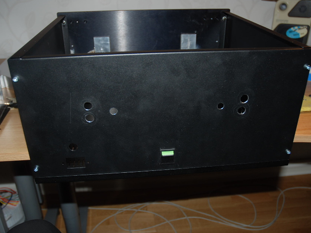
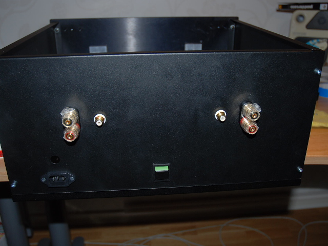
Most of the metalwork is now done.
It's time to assmeble everything...
Some more holes are needed, but will drill them when I know where to place everything. It's not lots of space left now...
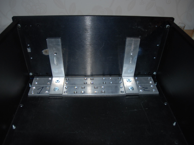
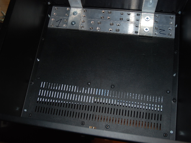
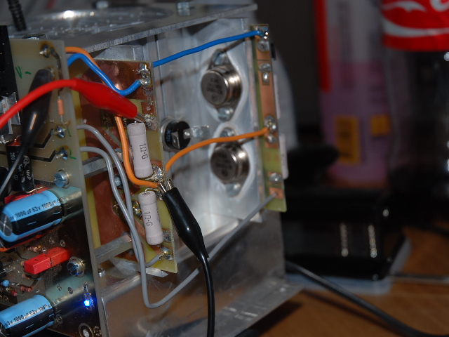
My trafo solution, not nice but it works.
I tried to weld first, but the metal is unkown, and it did not work.
Also need to reinforce the bottom, due to the big trafos.
Don't ask me why there are that many holes...
It's time to assmeble everything...
Some more holes are needed, but will drill them when I know where to place everything. It's not lots of space left now...
My trafo solution, not nice but it works.
I tried to weld first, but the metal is unkown, and it did not work.
Also need to reinforce the bottom, due to the big trafos.
Don't ask me why there are that many holes...
WOW fix I have read every post on this thread!.Pierre from south africa started on a high and delivered....later mark dropped everyone.What I noticed however is that Pierre's audiophile buddy was going to get a full blast version and up to now havent heard a word....just continued ramblings about his genuine Krells .So please continue so we get a real working example 3 years down the line without someones self claimed audio ears laying comments all the time..BRILLIANT FINNISH THE PROJECT
.So please continue so we get a real working example 3 years down the line without someones self claimed audio ears laying comments all the time..BRILLIANT FINNISH THE PROJECT browsing hifi2000.it pezante dissipante chassis I find http://www.modu.it/CARATTERISICHE_TERMICHE_DISS.pdf
they spec heatsink of 0.23 c/w to have max of 290 W dissipation
can I use It for passive cooling with krell clone 100 mk2
they spec heatsink of 0.23 c/w to have max of 290 W dissipation
can I use It for passive cooling with krell clone 100 mk2
@Seafire,
Thank you for your kind words...
It's been a long ride for this project, and now it looks like it will be finished atlast.
This is a real DIY Project where most parts needed had do be manufactuered by hand.
I think I've documented everything so I can reuse everything again to make more parts.
It's been fun, and time consuming... But worth it.
I'll keep you all updated..
no.samoloko said:they spec heatsink of 0.23 c/w ...........................can I use It for passive cooling with krell clone 100 mk2
You must de-rate the heatsink for the actual deltaT that will apply.
You must add on your ambient temperature.
You must de-rate your output stage devices for the actual Tc that applies.
With all this information and correction you will probably need a sink <=0.09C/W
Seafire
My project lost some steam after I took my monoblock heatsinks to an expensive metal shop and the quality of their work turned out worse than a DIY backyard job.
My preference now lies with the fan tunnels - due to their compactness. If I can find a set of fan tunnels - preferably larger than the standard Krell versions my project will be on track. If that fails I am scouting for a nice run down amp enclosure that could benefit from a Clone transplant. The last thing I want is to spend big bucks and put all of it in a crappy enclosure.
I suspect that once Fix provides feedback re the sound- everybody will get fired up again.
Regards
Jozua

@Jozua:
hmmm then the preasure is on me now...
This is my first Amp project...
- - - -
UPDATE:
After some setbacks last night, I completed one channel.
Did some initial testing before today, and everythings looks good.
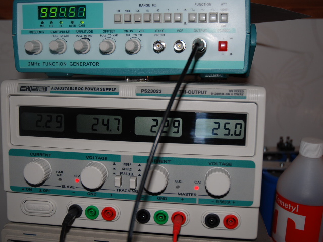
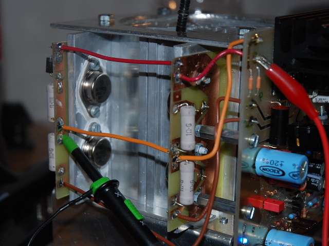
50VDC, 575mv over Emitter and 2.3Amp of current.
Heatsinks get about ~50* C without fan, after 15min
Will test with Fan tonight and run it for 2-3hours.
Will post pictures later today.
hmmm then the preasure is on me now...
This is my first Amp project...
- - - -
UPDATE:
After some setbacks last night, I completed one channel.
Did some initial testing before today, and everythings looks good.
50VDC, 575mv over Emitter and 2.3Amp of current.
Heatsinks get about ~50* C without fan, after 15min
Will test with Fan tonight and run it for 2-3hours.
Will post pictures later today.
Testing....
Tested for about 1h... will let it be on for another hour tonight...
VCC: 50v - 2.54amp
Emitter: 625mv
Heatsink: ca: 36C with fan at full speed
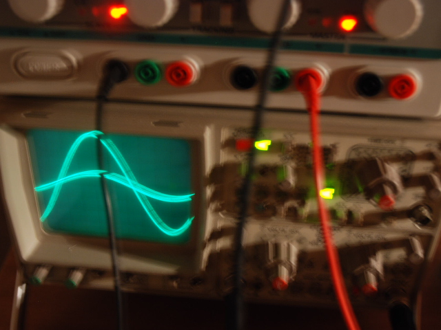
In/Out signal 1Khz
In: 0.1v / square
Ut: 0.5v / square
Pictures are taken before I went up to 625mv
Question: is the emitter voltage supposed to drop 0.1-0.3v when getting hot ?
If I turn pot up again to 625mv then it after 5min drop 0.1-0.2v..
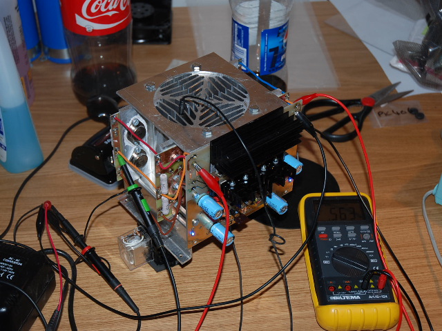
Guess something isn't stable in my powercube or signalgenerator.
** Just touched my powercube, it's super hot ... hahaha...
Hope it won't burn up...
Question 2:
Is it normal that the emitter voltage is NOT the same on all transistors ?
625mv
618mv
630mv
622mv
.....
Tested for about 1h... will let it be on for another hour tonight...
VCC: 50v - 2.54amp
Emitter: 625mv
Heatsink: ca: 36C with fan at full speed
In/Out signal 1Khz
In: 0.1v / square
Ut: 0.5v / square
Pictures are taken before I went up to 625mv
Question: is the emitter voltage supposed to drop 0.1-0.3v when getting hot ?
If I turn pot up again to 625mv then it after 5min drop 0.1-0.2v..
Guess something isn't stable in my powercube or signalgenerator.
** Just touched my powercube, it's super hot ... hahaha...
Hope it won't burn up...
Question 2:
Is it normal that the emitter voltage is NOT the same on all transistors ?
625mv
618mv
630mv
622mv
.....
Yes, the emitter resistors must be matched to better than 1% if you intend to use them as a measurement standard at a later stage.
I aim for better than 0.1% across all parallel pairs/sets of resistors.
Then I know I can rely on measurements thereafter. This really does show up transistor matching. Output sets must run with the base voltage equal for all. You can then measure emitter current and how it varies as bias is altered.
I'll keep it as it is, since the variation is minor.
Guess it would be hard to get 100% from both channels.
And I don't want to take everything apart once more....
- -
Anyway, I hooked up an old speaker 4ohm (just element) and used my computer as source..
It sounds crap...
When I use my signalgenerator it sound better, and not distorted.
But I can't get high output... ?!
When I raise the volym the Amp meter on my powercube lowers down to 0.5amp ( when speaker is connected )
1. I have serious problem with the amp.
2. My Powercube CAN'T drive my amp and that why I get those readings.
I guess the Powercube isn't build for driving a Class A amp...
But it's rated at 3Amp, guess that's why we need a 1000VA trafo rated 12amp @ 40v ?
Any ideas ?
Hi,
is the KSA100 Klone biased to 2.6A?
A push pull ClassA output stage driven to it's ClassA current limit, will draw ~5.2Apk from each rail alternately. That's 100W of ClassA into 8r0.
How the .... can you expect a 3A supply to even let the Klone run in ClassA?
What happens when you ask the amp to transit into ClassAB? Yes ask the Klone to deliver 55W into 4r0.
The rails currents become even bigger.
Another issue may be the way your power is connected. It looks like the power supply is connected to the rails without a ground. Floating the amp's ground may work for some instances, but using a single ended source, like the PC probably won't work out well.
If the two psu sides are truly independent (no terminals are connected to any other or ground when you select independent operation), you can create a proper split supply. Use the positive supply terminal to ground for the negative rail. Then tie the negative terminal of the other side to ground and you have the positive rail.
Of course, that doesn't alleviate the current limiting issue Andrew pointed out, but you should be able to listen at low levels.
For what its worth, the KSA-50 I built initially had the signal ground floating, and it sounded horrible too.
I think the bias and DC offset were not stable either without signal ground connected correctly.
Also, the amp ran quite hot when it was connected incorrectly too.
Once signal ground was correctly connected, all was perfect.
I think the bias and DC offset were not stable either without signal ground connected correctly.
Also, the amp ran quite hot when it was connected incorrectly too.
Once signal ground was correctly connected, all was perfect.
Bob & Fix,
that 5.2A ClassA current limit gets used up very quickly.
eg. 4ohm highly reactive speakers that draw (at low level output signal) enormous peak currents.
Let's assume that we have a peak current on fast transients of around ~ Volts peak/Load/0.35
For a 5Vac signal, that comes to 5.05Apk.
5Vac is only 6W into 4r0.
That is not much of a peak transient if you happen to be listening at an average level of 1W.
Yes, 4ohms speakers will run out of ClassA current at very low listening levels even when the Klone is biased to 2.6A through the output stage.
The 3A supply will similarly run out of current at very low listening levels. 3A has a margin of just 400mA above the bias current.
One rail could be supplying 3A and the other rail will have gone down to 2.2A. The difference between these rail current passes through the speaker and returns to audio ground.
800mApk is equivalent to 1.28W into 4r0. that is a transient peak of +1dB above 1W output.
All amplifiers need adequate current supplies to meet domestic music listening requirements. Don't skimp on the PSU because the ill informed have said it's not necessary.
- Home
- Amplifiers
- Solid State
- Krell KSA 100mkII Clone