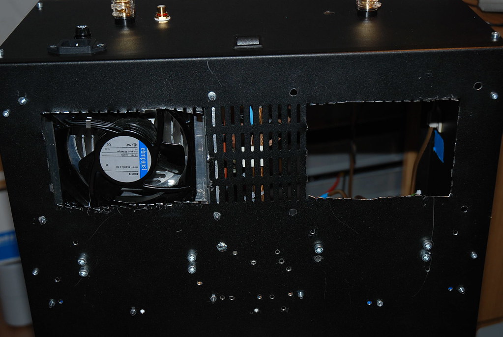
Here is a picture from the bottom.
** It's not nice... Before this surgical cut, the amp got super hot..
So it was needed to get in more air...
The top is perforated in a similar way, over the whole top.
Right now I think that I get in "too much" air, than I can get out.
And the hot air stays in...
Some "air noise" is proably because the path in not big enough in bottom.
Guess I have to take apart everything again... and cut a bigger hole.
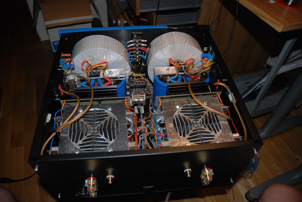
Yes, I used 1pair 2sa1360/c3423 pre-drivers, 2pair 2sb649/d669 drivers and 6pair MJL4281/4301 outputs.Harry3 said:Hi Andrew,
didn't you use faster transistors in your amp? Might this be the problem?
Been testing now to put a 250ohm resistor to one of the fans.
Heatsink temp after ~1.5/2h playing
Fan 1 + 250ohm: ~56-57c
Fan 2 + Fullspeed: ~52-53c
Roomtemp: ~25c
Noise from Fan 1 with resistor is much much lower, I would have to say 30-50% lower... That low so I think no one can complain.
Fan 2 is way to loud.
Question.
How hot is ok for heatsink ?
I will take everything apart soon as I can, and cut intake to match the fan size 120x120mm for maximum air intake.
Now I have ~120x80mm
I've used
Q14-Q17, MJE15030 & MJE15031
MJ15003 & MJ15004
Heat issue
Fix
I have often wondered if one cannot use the existing four screws of the Krell heatsink block to clamp another heatsink with vertical fans (of which a circular hole has been milled out in the center baseplate) on top of the current heatsink blocks ?
In the Mk 1 version the heatsink blocks were mounted directly on the chassis which also absorbed a lot of heat.
Krell has the tools to very accurately match their components and ensure that it is used well within their safety range. With the average DIY builder you do not have that safety margin and therefore need to take extra care with heatsinking.
Regards
JH
I did saw two now holes yesterday, 130x130mm.
Now the fans have no restrictions in the air intake.
I also connected a 250ohm resistor to each fan.
The fan noise is much much better, and I guess it would be hard to get it lower.
I've used the most quiet fan I found from Papst, maybe a higher value on 500ohm could lower the speed even more...
After ~2h i had 53c on the heatsinks, so this is much better.
Will test more tonight. ( without cover... ) Since airflow is lower, I hope there would be no problem when cover is on.
I've tried to read the datasheet on the MJ15003/4 transistors.
To figure how much heat the can take before breakdown.
50v, 5amp = Safe ???
Without heatsink ?
Also it looks like it can take 200c ???
Can anyone help me out here... You can find datasheet at mouser.com
50Vce and Ic=5A cannot be safe at any temperature above Tc=25degCFix said:50v, 5amp = Safe ???
Without heatsink ?
I think you've pulled out the wrong numbers.
I have modelled a temperature de-rated SOAR on a 4pair MJ15003/4 output stage with Tc<=67degC and the 4ohm 60degree phase angle load line is comfortably below the ONsemi DC SOA.
I assumed +-50.5Vdc , +-60mF, Re=1r0, regulation 3.5%
Ts ~= Tc-10Cdegrees, i.e. Ts~=57degC
The model predicts 230W into 4ohm all day long and 400W into 2ohm for intermittent duty (music into a severe reactance speaker).
.... That's why I need some help understand the data sheet...
http://www.onsemi.com/pub_link/Collateral/MJ15003-D.PDF
It says:
High Safe Operating Area (100% Tested) − 5.0 A @ 50 V
What is Tc 25c*
What is Tj 200 C*
If I understand the chart correct.
TC is @25c ( room temp ? )
And Tj, (TO-3 Case, or just junction.. ?) @ 200c
Then it's safe to use 5A @ 50v
But I would like to know how hot can the heatsink get without the MJ15003 will burn...
What is the magic formula...
http://www.diyaudio.com/forums/showthread.php?postid=644195#post644195
Bensen gives a very good idea of the "magic formula"
I have a modified version that also does BJTs and Drivers as well as FETs.
Email me.
Note on page 2 of the 15003 pdf that the data is for Tc=25degC,
i.e. an infinite heatsink held at a temperature to ensure the case of the DUT is always @ 25degC
Bensen gives a very good idea of the "magic formula"
I have a modified version that also does BJTs and Drivers as well as FETs.
Email me.
Note on page 2 of the 15003 pdf that the data is for Tc=25degC,
i.e. an infinite heatsink held at a temperature to ensure the case of the DUT is always @ 25degC
to go back to a basic level, OnSemi says the junction temperature (Tj) can be 200C. The thermal resistance between the junction and case (Rjc) multiplied by the power dissipated in the device determines the temperature rise above case temperature.
In Andrew's infinite heat sink example, we maintain the case at 25C. Pump 250 watts into it (50V, 5 A) multiplied by Tjc of .7 and you get junction temperature 175C above the case, or 200C.
In real life, you are talking about nearly 60C on the sinks. There is a thermal resistance of roughly .7 between the sink and the case due to the isolator. For improved reliability you'll want to limit junction temperature to at least 50C below rated. Some say use 100C junction temperature, but most people are using 150C rated devices.
That means that you can only use enough power to raise the junction temperature 90 degrees. The thermal resistances junction to case and case to sink add, so expect a rise of 1.4 degrees per watt. Crunching the numbers 90C / 1.4C/W = 64W safe dissipation per device.
These calculations give results similar to the de-rating graphs in the data sheet.
This will give you a rough feel for how hard you can push your devices. SOA calculations are better.
I've found a Swedish page where the calculations are shown.
Tc 60 Case Temp
Tj 200 Junction Temp
Tjc 0,7 C/W TO3
P 200 Watt
Tc = Tj - Tjc * P
If I get it, Case temp @ 200W must not be over 60c
This is for 1x TO-3 MJ15003, and we're using more in this amp, so each transistor is @ 25w ?
And then 25c @ 250W / 50V/5A is True... needed to keep under 25c...
To make it easy, keep heatsink under 60c then there will be no problem at all.
Am I right ?
Fix said:
Tc = Tj - Tjc * P
That means the device case is at 60C - there is another P * Tcs (case to sink thermal resistance) to contend with. At 200W/device this is roughly another 140C, so you can be safe operating at 200W on a sink at -80C. Easy to do with a bit of liquid nitrogen.

With each device at 25W (.5A @50V), you'll see ~35C rise from sink to junction. From a steady state dissipation perspective you are safe on a 60C sink.
However, we aren't using amps at steady state DC conditions, and you need to compare your load line to the device's SOA to really know if you are safe.
Tc = Tj - Tjc * P
60 = 200 - 0,7 * 200
I've read the text again, and it says that Device Case shall not exced over 60C to be safe.
If you take same formula
25 = 200 - 0,7 * 250
Same as rated in data sheet TC = 25C @ 250W
So if you want to use 250W, TC shall not get over 25C with cooling ?
Here is the link
http://web.telia.com/~u93007940/
It also describes how to calculated size of heatsink etc.
I cannot read Swedish, so I cannot directly comment. However, it seems that the author you cite has made two assumptions that are not valid in the real world (or you have misread him).
First, he assumes that you want to run your devices right at their maximum ratings. This is a bad idea. For the sake of reliability you want to keep your devices significantly cooler than their maximum rated temperature. The cooler they are the less likely they are to fail. Not alll devices will operate reliably at their rated maximums.
DIYers (and smart people like Nelson Pass) often use 50% of maximum rated as an operating point. That's why I recommended a target maximum junction temperature of 150C for your 200C rated devices.
Second, your reference (or the way you are reading it) ignores the fact that there will be a temperature rise between the heat sink and the device case. Not likely to happen in the real world. Even if you don't use an isolator. you will get some thermal resistance between the sinks and the case. Some isolators do better than the .7C/W that I used as an example, some worse. You need to take that rise into account.
Edit: (can any swedish speakers help here?)
Looking at Mathias' page I think you missed his reference to the thermal resistance from the case to sink - there are three factors getting from junction to air in this equation:
http://web.telia.com/~u93007940/
First, he assumes that you want to run your devices right at their maximum ratings. This is a bad idea. For the sake of reliability you want to keep your devices significantly cooler than their maximum rated temperature. The cooler they are the less likely they are to fail. Not alll devices will operate reliably at their rated maximums.
DIYers (and smart people like Nelson Pass) often use 50% of maximum rated as an operating point. That's why I recommended a target maximum junction temperature of 150C for your 200C rated devices.
Second, your reference (or the way you are reading it) ignores the fact that there will be a temperature rise between the heat sink and the device case. Not likely to happen in the real world. Even if you don't use an isolator. you will get some thermal resistance between the sinks and the case. Some isolators do better than the .7C/W that I used as an example, some worse. You need to take that rise into account.
Edit: (can any swedish speakers help here?)
Looking at Mathias' page I think you missed his reference to the thermal resistance from the case to sink - there are three factors getting from junction to air in this equation:
An externally hosted image should be here but it was not working when we last tested it.
http://web.telia.com/~u93007940/
Först effekten:
formel6.gif (1,1 Kb)
TJ är kristalltemperaturen (max 175 °C)
TO är rumstemperaturen (25-50 °C) TJC är JUNCTION TO CASE värmeledningen (°C/W för TO-3=1,2 och för TO-220=2)
TGK är värmelednigen från transistorhölje genom luft, glimmerskiva och kiselfett. Luft beräknas vid normal sammansättning till 0,3 och glimmerskiva till 0,7. Påläggs kiselfettet på båda sidor om glimmerskivan förbättras egenskaperna 0,2-0,3.
TK är kylflänsens "till luftström" värmeledning. Dess storhet är helt beroende av profilutseende och storlek.
Hi,BobEllis said:An externally hosted image should be here but it was not working when we last tested it.
Tjc = Rth j-c (junction to case)
Tgk = Rth c-s (case to sink)
Tk = Rth s-a (sink to ambient)
You need to find the values of these three resistances and then find what power you want/need to dissipate
- Home
- Amplifiers
- Solid State
- Krell KSA 100mkII Clone