Done. The voltage follows the tube. That is, when I swap the tubes between channels, the .75V at the 12AY7 cathode moved from L to R.
Also, I made an error reading one of the voltages-- there's 145V at the 6N23P pin 1 on one channel and 160V on the other. This difference also follows the 12AY7 when swapped.
Bad AY7s?
Kofi
Also, I made an error reading one of the voltages-- there's 145V at the 6N23P pin 1 on one channel and 160V on the other. This difference also follows the 12AY7 when swapped.
Bad AY7s?
Kofi
The grounded cathode looks fine. The difference between the expected 102V and the measured 115, is right in line with the difference in your supply voltage and that of Steve's schematic.
Something is definitely fishy with the cascode. In channel 1, the current is low. From your measured values, it appears to be about 0.36mA. Should be around 0.6mA. This is regulated by the AY7 and it's cathode resistor. Recheck the resistance from cathode to common ("ground"). However, the current through the cascode top and bottom match up.
The really fishy part is that the current across the plate resistor for the channel 2 cascode is higher than the current through the cathode resistor for the cascode. Those two resistors are in series in the circuit, so they must have the same current. Likely culprit could be a leaky bypass cap.
Like Salas said, flip flop the AY7s and see what you get for the cascode voltages.
Sheldon
You posted while I was writing. Yes, if a problem follows the tube, that tube is a problem. Let's see what happens with two good tubes. Still think current is a bit low for the cascode.
Kofi Annan said:Lower gain follows. I'm not sure about the power down ZZZZZZZZZZZZIP! anymore as I have been shutting down the amp before the preamp to save my speakers.
No big deal. I'll bag another pair and try again.
Thanks for the advice!
Kofi
Great. Are the current ones NOS, or EH new model? One thing more:
Remember, with my final low impedance pad and new EMU card, I have found 6n8 (6800pF) C1 to match my Simplistic NJFET and Valve Itch Riaa curves. All other values as per original Steve Bench schematic.
Tubes arrived on Wednesday and I put them in this morning!
THE GOOD NEWS
All voltages appear to check nearly dead on to the Bench schematic (Note: I adjusted the HT supply to 185V to match Bench's supply for the time being). So, it appears, it was the tubes after all!
THE NOT-SO-GOOD-NEWS
I have a wicked hum right now and the ZZZZZZZZZZZZZIP! is still happening at power down. I've never heard anything like that sound before, so I wonder if there's a signal grounding problem that's causing both the hum and the ZZZZZZZZZZZZZIP!
I'll start the hum investigation this afternoon, but I'm really encouraged by the voltage checks.
Yeah!
Kofi!
Kofi Annan said:THE NOT-SO-GOOD-NEWS
I have a wicked hum right now and the ZZZZZZZZZZZZZIP! is still happening at power down. I've never heard anything like that sound before, so I wonder if there's a signal grounding problem that's causing both the hum and the ZZZZZZZZZZZZZIP!
I'll start the hum investigation this afternoon, but I'm really encouraged by the voltage checks.
Yeah!
Kofi!
Haven't heard that Zzzzzip, sound with the Bench and the HV shunt myself. Don't you have a volume control in between phono and power stage right now? You wrote above that the zzzip was coming out of one channel only. Is it in stereo now? If in one channel still, then can't be a supply transient. Would be in both channels. In general, we don't shut down things without some means of mute (mute switch, volume at -infinity), when the power stage is on. Transients can happen. Maybe its your choke loaded prefilter's magnetic energy collapsing? The shunt does not have output capacitor, and if the input cut off is dramatic, don't know, it maybe turns off ''in style''
 ? Also the series heater arrangement can interact? Don't know again, but surely you have to turn off power amp first or use volume cut off. I agree with Sheldon that your real and now problem is the hum. And it can be zip related too.
Salas is right that the zip may be related to the hum issue. But a practical reason to focus on the hum, is that it is continuous, so much easier to probe.
First, measure all your point to point resistances with the phono amp off, and make sure that they make sense. Second, get a magnifying glass and look at all your solder joints to make sure you have no obvious weak joints. Third, probe all your solder joints mechanically to make sure nothing is loose.
Now the live testing. If you have a scope, you can use that to display the output. If not, a speaker is fine. Best is a cheap surplus driver, although with a relatively low powered tube amp, there aren't many speakers you can blow up, even if you make awful sounds. Actually I prefer a speaker at first, because I don't have to look at it while I'm testing.
Now power up and measure all voltages (you've done this, already I think, but at least a quick second check is in order). With your scope or speaker and amp connected to the output, you can begin checking your grounds. Make a probe like a DVM probe, but with a clip at the other end. Best is to have a small value inline fuse (50mA or so is fine, as you should not have any significant current going through the probe if your circuit is proper. The fuse will protect the circuit if you accidentally touch the wrong thing. If you find something, you can retest the same two points without the fuse, or with a plain clip lead. If you use a plain clip lead, turn off the power, clip up, then turn on.).
Attach the clip to your common (or main star, if you did a star ground arrangement). Carefully start touching the probe to the various circuit ground points and look or listen for any changes in the hum volume. Be safe and work slowly. One hand only holding the probe, the other behind your back. Make sure you are only probing ground connections. If you have a wire more than a couple of cm long that is part of the ground circuit, test several points along the wire. Start this process with your power supply, then the preamp. Try it with the probe clipped to the common, the chassis, the earth. You're bound to find something that increases or decreases the hum level. Now you have something to analyse.
Sheldon
Hi everybody,
What a great thread this is!! Thanks to it I built the Steve Bench phono preamp a couple of months ago and today I finished the Salas HV shunt regulator. At first I was driving the preamp with a simple TL-783 IC regulator and I wasn’t very happy because some noise was coming thru the speakers. At first I thought it was the valves but changing to EH 12AY7s and 6N23Ps didn’t cure the problem.
Reading the main thread on the Salas HV shunt, I upgraded to a Maida regulator using the layout described by Gaime but wired point-to point. The improvement was very noticeable, almost dramatic! Gone was the background ‘valve’ noise and the instrument came out naturally and sharply. Encouraged by my success I went a step further and built the Salas Shunt reg. I used Gary Pimm’s layout on a p-2-p pre-punched circuit board. It worked first time!! Thanks a lot Gary!!
I have to say that the difference from the Maida wasn’t immediately noticeable but as the unit warmed up (and maybe my ears got used to it) the sound mellowed up, bass got tighter and the highs more articulated. The ‘shunt’ sound is more relaxed whereas the Maida was slightly more aggressive. Somehow, to these ears the sound is more ‘valvey’, which is OK by me. Silent passages are ‘blacker’ and even record surface noise seems to have improved.
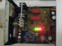
I built the regulator exactly as described in this thread, with 56 ohms (instead of 33) for R1. I’m using red LEDs (ideally there should be around 5.4V across them) but I haven’t checked them. All I know is that I have around 186-188V output feeding my SB preamp which is what is needed after all! I don’t have any heating problems with the heatsinks either – just warm to the touch. R9 is the component that gets really hot but I haven’t had any problems so far. But I will try green leds to see if there are any changes. Probably not, but for the time being I will continue to enjoy the sound for quite a few more hours, something which has eluded me with the previous power supplies!!
So, A BIG THANK YOU to all who have contributed to this thread and especially SALAS who has given us an excellent HV regulator!!! As one with very limited knowledge, experience and test-gear I encourage anyone interested in this thread to build both the preamp and the HV shunt regulated PS. More information and construction details about the supply can be viewed at: http://www.diyaudio.com/forums/showthread.php?s=&threadid=134801&highlight
Joe A
What a great thread this is!! Thanks to it I built the Steve Bench phono preamp a couple of months ago and today I finished the Salas HV shunt regulator. At first I was driving the preamp with a simple TL-783 IC regulator and I wasn’t very happy because some noise was coming thru the speakers. At first I thought it was the valves but changing to EH 12AY7s and 6N23Ps didn’t cure the problem.
Reading the main thread on the Salas HV shunt, I upgraded to a Maida regulator using the layout described by Gaime but wired point-to point. The improvement was very noticeable, almost dramatic! Gone was the background ‘valve’ noise and the instrument came out naturally and sharply. Encouraged by my success I went a step further and built the Salas Shunt reg. I used Gary Pimm’s layout on a p-2-p pre-punched circuit board. It worked first time!! Thanks a lot Gary!!
I have to say that the difference from the Maida wasn’t immediately noticeable but as the unit warmed up (and maybe my ears got used to it) the sound mellowed up, bass got tighter and the highs more articulated. The ‘shunt’ sound is more relaxed whereas the Maida was slightly more aggressive. Somehow, to these ears the sound is more ‘valvey’, which is OK by me. Silent passages are ‘blacker’ and even record surface noise seems to have improved.
I built the regulator exactly as described in this thread, with 56 ohms (instead of 33) for R1. I’m using red LEDs (ideally there should be around 5.4V across them) but I haven’t checked them. All I know is that I have around 186-188V output feeding my SB preamp which is what is needed after all! I don’t have any heating problems with the heatsinks either – just warm to the touch. R9 is the component that gets really hot but I haven’t had any problems so far. But I will try green leds to see if there are any changes. Probably not, but for the time being I will continue to enjoy the sound for quite a few more hours, something which has eluded me with the previous power supplies!!
So, A BIG THANK YOU to all who have contributed to this thread and especially SALAS who has given us an excellent HV regulator!!! As one with very limited knowledge, experience and test-gear I encourage anyone interested in this thread to build both the preamp and the HV shunt regulated PS. More information and construction details about the supply can be viewed at: http://www.diyaudio.com/forums/showthread.php?s=&threadid=134801&highlight
Joe A
Thanks for practicing my HV shunt. Nice to know it worked for you too. The shunt opens up its sound more, after 48h of use. R9 is supposed to be hot, no problem. Just keep it high enough from board. Don't change LEDs color since it works OK with red. Noise is about the same, or better. I suggest green bcs they are more predictable for nominal Vdrop each. That, can be critical in higher currents and voltages so not to end up running much hotter than needed.
Did you change C1,C9 on Bench schematic to 6800pF? I have found it to work correctly with that value. With original 5700pF value, it measures more treble than it must on my FFT.
P.S. Can we see pictures of your SB RIAA and HV Shunt?
Did you change C1,C9 on Bench schematic to 6800pF? I have found it to work correctly with that value. With original 5700pF value, it measures more treble than it must on my FFT.
P.S. Can we see pictures of your SB RIAA and HV Shunt?
Hi Salas,
Regarding the Steve Bench phono, yes I used 6n8 for C1,C9.
As to burning-in, it is true, the second time I switched it in it sounded 'closed-in'. After about 15 hrs more service it sounds better. Anyway, I am very happy with the sound of the combination Steve Bench phono - Salas HV Shunt regulator. I've built quite a few phonos and I think this is the best so far.
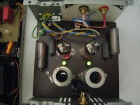
I attach a photo of HV shunt regulator.
Joe A
Regarding the Steve Bench phono, yes I used 6n8 for C1,C9.
As to burning-in, it is true, the second time I switched it in it sounded 'closed-in'. After about 15 hrs more service it sounds better. Anyway, I am very happy with the sound of the combination Steve Bench phono - Salas HV Shunt regulator. I've built quite a few phonos and I think this is the best so far.
I attach a photo of HV shunt regulator.
Joe A
Attachments
Floating the heaters -- How to d-i-y?
I recall reading that the SB phono would benefit from a floated heater supply. I'm not sure how to do it but from reading other posts it seems we want to pass around 1mA or more across the B+ - 185V - (in my case supplied by the Salas HV shunt regulator). Then we make a potential divider, the lower leg of which carries the floating voltage.
I calculated the potential divider for a floating voltage of 50V. The upper resistor (connected to B+) is 120K while the lower is 47K paralled by a 100uF/100V electrolytic cap, and to which the filament DC+ is connected. I've attached a Word file which I hope makes it simpler.
Your comments would be much appreciated. Thanks.
Joe A
Attachments
- Status
- This old topic is closed. If you want to reopen this topic, contact a moderator using the "Report Post" button.
- Home
- Amplifiers
- Tubes / Valves
- Kofi Annan in: "Cascodin' with Steve Bench's RIAA!"