What happens when a normally on (deplMOS) device receives B+ and the tube tied on its gate isn't conducting to expected plate drop yet?
The gate will see the full B+, as will the source resistor. Of course the resistor must be spec'd to handle the power until the tube conducts and the FET has to pass the resulting current. It's not much different from an enhancement mode device. Until the tube conducts, the source resistor will see B+, minus about 4V.
Sheldon
He mentioned he lost the source resistors, so I am afraid the problem starts there.
If the resistors failed as a short, then the FET could be toast (they usually fail open). But that doesn't explain the odd voltage readings for the amp. At this point, I'm questioning the meter.
Sheldon
He had a nicely working Bench, only he needed better coupling to his line pre in the lows. Then he drops in a Supertex follower, lets the smoke out there, and the tube circuitry measures bonkers? Unlikely. I hope there is no capacitor coupling left there between plate and follower.
He had a nicely working Bench, only he needed better coupling to his line pre in the lows. Then he drops in a Supertex follower, lets the smoke out there, and the tube circuitry measures bonkers? Unlikely. I hope there is no capacitor coupling left there between plate and follower.
Yes, the tube measurements don't add up. Even if the follower failed and the resistor failed short (unlikely, they act more like fuses), the only component likely to fail before that would be the plate resistor to the output tube. We'll see what his testing shows.
Sheldon
So you've been discussing my problem... Thank you guys!! Not that I have positive things to report. Changed batteries of both meters (analogue and dmm) and first checked all resistors in circuit. They all are within their tolerance except R1 and R4 (using SB's schematic, with a grn led replacing C8-R16). These are my in-circuit resistance readings (with PS off!):
R1 = 180K (124K /121K)
R4 = 150K (110K / 90K) both of them being 0.5W. I also checked them out of circuit and they were spot on on the required value.
Voltage readings however (SF disconnected) remain baffling as ever. For example on the analogue meter (Avo Mod 7A) with new battery I was reading different values on 120V and 480V. My dmm readings were even more ridiculous! The meter figures keep moving up and down (sign of instability?) - I'll order a new one. Anyway, these are the readings on my Analogue meter set on 480V which are closest to the test voltages:
Supply Voltage: 180V ~ 185V
Ecc88 pin 6 = 102v : 85V / 110V
ecc88 pin 1 = 123v : 70V / 70V
ecc88 pin 2 = 85V : 40V / 40V
ecc88 pin 8 = 2.5v : 2v / 1.4V
12ay7 pin1-6 = 87V : 70V / 70V
12ay7 pin3-8 = 1.91: 1.6V/ 1.5V
Sorry if this is getting frustrating.
Joe A
I'm beginning to question the test gear. Before you go much further, make sure that this is not an issue. Unless your measurements are reliable, they are worth less than nothing. They can lead you down the wrong path. Do you have a known good meter that you can borrow from somewhere, or at least compare your meter with? That said:
First: Don't worry about frustrating us. We're here to help. This is just a puzzle to solve - and it will be solved.
If the two channels are connected together at the supply, or if the supply has a DC path to common, then you will get lower measurements. That's because you have parallel paths to your common. But you should see the same values for both channels. Your different measurements for R4 make me wonder if the decoupling cap on the side with the low reading is leaking current. Disconnect it and see what you get. I would recommend measuring each channel separated from each other and the supply. This makes tracking problems easier.
Voltage at pin 6 and 2 varies more than I'd like, but that doesn't necessarily signal a problem other than fairly poor tube matching. Switch the tubes from channel to channel and see if the measurements follow. What is an issue, is that the current doesn't add up. Take the first side 85V/2V, plate/grid: The current through the plate resistor is 5mA. But the calculated current through the cathode resistor is 3.6mA. These currents should match. Similar issue on the other channel.
The pin 2(grid to the top tube in the cascode) measurement is a real problem. First, remove the EC88 from the circuit and measure the voltages at pin 1 and 2. Remember that your shunt supply will have to shunt all the current now, so just take the measurement and don't let it run like this longer than necessary. Don't want to overheat the supply.
Now the measurement for the AY7: You've measure the EC88 plate at 70V. You also get 70V at pin 1,6 for the AY7. Since these are connected directly to the EC88 cathode, then the voltage at the plate of the EC88 is the same as the cathode - or a dead short. This can't be, unless you've got wires crossed, or the socket wired wrong, or an internal short in the tube. The latter two can be ruled out, since you had the amp working, and there's no way it would work with the socket wired wrong or the tube shorted. Again this suggests a measurement error. The other piece of evidence that suggests this is the voltage at your AY7 cathode. Your measurements are lower than what would be expected from a green LED (about 1.8V) alone, much less in series with a 400R. If your LED is giving off a decent amount of light, then it should measure around that value.
Keep plugging. We'll sort this out.
Sheldon
They all are within their tolerance except R1 and R4 (using SB's schematic, with a grn led replacing C8-R16). These are my in-circuit resistance readings (with PS off!):
R1 = 180K (124K /121K)
R4 = 150K (110K / 90K) both of them being 0.5W. I also checked them out of circuit and they were spot on on the required value.
First: Don't worry about frustrating us. We're here to help. This is just a puzzle to solve - and it will be solved.
If the two channels are connected together at the supply, or if the supply has a DC path to common, then you will get lower measurements. That's because you have parallel paths to your common. But you should see the same values for both channels. Your different measurements for R4 make me wonder if the decoupling cap on the side with the low reading is leaking current. Disconnect it and see what you get. I would recommend measuring each channel separated from each other and the supply. This makes tracking problems easier.
Voltage readings however (SF disconnected) remain baffling as ever. For example on the analogue meter (Avo Mod 7A) with new battery I was reading different values on 120V and 480V. My dmm readings were even more ridiculous! The meter figures keep moving up and down (sign of instability?) - I'll order a new one. Anyway, these are the readings on my Analogue meter set on 480V which are closest to the test voltages:
Supply Voltage: 180V ~ 185V
Ecc88 pin 6 = 102v : 85V / 110V
ecc88 pin 1 = 123v : 70V / 70V
ecc88 pin 2 = 85V : 40V / 40V
ecc88 pin 8 = 2.5v : 2v / 1.4V
12ay7 pin1-6 = 87V : 70V / 70V
12ay7 pin3-8 = 1.91: 1.6V/ 1.5V
Voltage at pin 6 and 2 varies more than I'd like, but that doesn't necessarily signal a problem other than fairly poor tube matching. Switch the tubes from channel to channel and see if the measurements follow. What is an issue, is that the current doesn't add up. Take the first side 85V/2V, plate/grid: The current through the plate resistor is 5mA. But the calculated current through the cathode resistor is 3.6mA. These currents should match. Similar issue on the other channel.
The pin 2(grid to the top tube in the cascode) measurement is a real problem. First, remove the EC88 from the circuit and measure the voltages at pin 1 and 2. Remember that your shunt supply will have to shunt all the current now, so just take the measurement and don't let it run like this longer than necessary. Don't want to overheat the supply.
Now the measurement for the AY7: You've measure the EC88 plate at 70V. You also get 70V at pin 1,6 for the AY7. Since these are connected directly to the EC88 cathode, then the voltage at the plate of the EC88 is the same as the cathode - or a dead short. This can't be, unless you've got wires crossed, or the socket wired wrong, or an internal short in the tube. The latter two can be ruled out, since you had the amp working, and there's no way it would work with the socket wired wrong or the tube shorted. Again this suggests a measurement error. The other piece of evidence that suggests this is the voltage at your AY7 cathode. Your measurements are lower than what would be expected from a green LED (about 1.8V) alone, much less in series with a 400R. If your LED is giving off a decent amount of light, then it should measure around that value.
Keep plugging. We'll sort this out.
Sheldon
Last edited:
More decent voltages !!!
Just came down to report voltages with another (discarded dmm, DT830B which I thought was crap compared to another more fancy dmm). Thank you so much, Sheldon. Just saw your reply but haven't followed it yet, because I see more meaningful figures right now:
Supply Voltage: 178.3 (L) 178 (R)
Filament: 5.59 (L) 4.32 (R)
ecc88 pin 6 = 102V : 96.1 (L) 127V (R)
pin 1 = 123V : 122.7 (L) 127.1 (R)
pin 3 = 87V : 81.8 (L) 82.1 (R)
pin 8 = 2.4V : 2.28 (L) 1.28 (R)
12ay7 pin 3 = 1.91V : 1.91 (L) 1.91 (R)
You were right about the meters. Do these new readings tell you something new? Can the filament v difference influence the different readings between channels? Meanwhile I will see to your reply suggestions.
Thanks and regards,
Joe A
Do these new readings tell you something new? Can the filament v difference influence the different readings between channels?
Now we are getting somewhere. Yes, those values make a lot more sense. Your input cascode looks fine. There is a issue with the low conduction of the second section for the second channel, but at least the current is accounted for (a little off for the second channel, but let's look closer when we get the current closer).
Yes, it's possible that the heater filament is limiting at a little over 4V, as you are asking that section to move a fair amount of current. Your supply of electrons may be limiting. You need to work that out. BTW, my personal preference is simple voltage regulation for indirectly heated filaments. I see no benefit to constant current here. But let's sort out what you have for now. It's either the heater or the tubes. So move the tubes around and see what happens. Does the voltage variation follow the tube or not?
Sheldon
Moving on to next step
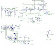
I have made a few adjustments, fixed the filament issue and I now have the SB phono working and measuring OK. Thanks Sheldon. Now comes the inclusion of the source follower (which had previously caused this last spate of posts). I still have to check the DN2540s but right now I want check whether I got the connections right. As there have been some doubts in previous posts I am attaching a schematic of my schema. I think I followed your circuit but I want to make sure it is wired correctly, particularly the protection diode orientation.
Thanks and regards,
Joe A
Attachments
I have made a few adjustments, fixed the filament issue and I now have the SB phono working and measuring OK. Thanks Sheldon. Now comes the inclusion of the source follower (which had previously caused this last spate of posts). I still have to check the DN2540s but right now I want check whether I got the connections right. As there have been some doubts in previous posts I am attaching a schematic of my schema. I think I followed your circuit but I want to make sure it is wired correctly, particularly the protection diode orientation.
My original instructions were not adequate. For a depletion mode device and this circuit, if you use a single diode, you'd actually want the diode to go from source to drain. Or you could use Salas' scheme. It's insurance for a wider range of circuits. But as he said, you can get by without it.
You want to make sure the gate to source voltage doesn't exceed the limit for this part, which is 20V in either direction. So you want to analyze possible failure modes:
At turn on, you have no problem with this circuit, since the gate and drain power up simultaneously. The FET will conduct instantly to bring the source voltage up near the gate voltage.
At turn off, if you had a large cap on the output, the voltage on the source could remain high while the gate voltage went to zero. This could exceed the gate to source rating. But the small cap you have will drain as fast as the power supply drains, so the source voltage will drop with the supply voltage.
A possible exception is if the connection from the supply to the amp is opened while the power is on. This could possibly create an instant drop in drain and gate voltage, but slower drop in source voltage due to the output cap. The probability of this is low, but I'd still be inclined to put a diode from source to drain as cheap insurance. Salas' method will work fine for this too.
Sheldon
Thanks Sheldon & Salas, you've been a great help and a source of knowledge. I've been listening to the stock SB phono with 6.8uF output coupling capacitor and the lower register has now solidified with more air. I was thinking whether it would benefit from a fully-fledged buffer amp between the SB Phono and preamp. I was thinking of the DC-B1 buffer in which Salas was involved. The input impedance is only 25K but it seems it can be increased to 50K which is the same as the preamp Zin I'm using.
There are then a number of valve buffers on this forum. Which is the best way to go if at all worth it for the SB Phono?
Any comments?
There are then a number of valve buffers on this forum. Which is the best way to go if at all worth it for the SB Phono?
Any comments?
Thanks Sheldon & Salas, you've been a great help and a source of knowledge. I've been listening to the stock SB phono with 6.8uF output coupling capacitor and the lower register has now solidified with more air. I was thinking whether it would benefit from a fully-fledged buffer amp between the SB Phono and preamp. I was thinking of the DC-B1 buffer in which Salas was involved. The input impedance is only 25K but it seems it can be increased to 50K which is the same as the preamp Zin I'm using.
There are then a number of valve buffers on this forum. Which is the best way to go if at all worth it for the SB Phono?
Any comments?
Get the source follower working first. It is a fully fledged buffer amp, and it's the easiest one you can do. Later, you can try something more exotic if you like. I'm not familiar with the DC-B1 but, in my opinion, pointless if the input Z is only 50k. You need at least 100k. If you want all tube, you've seen the Aikido buffer I use. With your power supply, you can leave off the canceling stuff on the output. All you need is a grid leak resistor for the bottom section, and output cap and bleed resistor for the output. Many other possibilities with the proper input impedance.
Sheldon
Last edited:
external power grounding
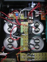
Just finished the external HV shunt as first step, I tied the case to power supply ground together with the shield of the power transformer. The power output is actually floating right now in reference with power supply ground. I noticed there was about 50V AC between the chassis and power output ground, should I link them together with 0.1U capacitor? I have concern of ground loop if I connect the power output ground directly to the chassis.
Just finished the external HV shunt as first step, I tied the case to power supply ground together with the shield of the power transformer. The power output is actually floating right now in reference with power supply ground. I noticed there was about 50V AC between the chassis and power output ground, should I link them together with 0.1U capacitor? I have concern of ground loop if I connect the power output ground directly to the chassis.
Attachments
Last edited:
Just finished the external HV shunt as first step, I tied the case to power supply ground together with the shield of the power transformer. The power output is actually floating right now in reference with power supply ground. I noticed there was about 50V AC between the chassis and power output ground, should I link them together with 0.1U capacitor? I have concern of ground loop if I connect the power output ground directly to the chassis.
Best to show a schematic of exactly how the commons and earth are tied together.
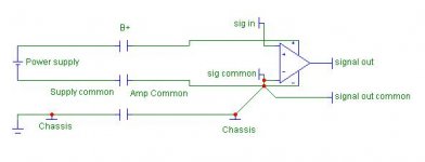
But here is the general way to do it. Let's talk about "common" and "earth" as two separate entities. Commons are the power and signal current returns. Earth is only the safety earth connection. I suggest that you earth the power supply chassis. Also run an earth connection from the RIAA chassis to the earth point on the power supply chassis. Star connect all your supply and RIAA commons at the RIAA amp (no common to earth connections at the power supply chassis). Run a single connection from this point to the earth connection in the RIAA chassis.
If you want, you can lift the common to earth connection with a resistor (10R or so), or with an anti-parallel diode pair. You may also want to use a small film cap across the resistor or diodes to shunt any RF noise to earth. I have found that if I am careful with the commons, that I don't usually need the lift. The exception may be, when you have interconnected devices that are on different mains circuits.
Sheldon
Here's an example. Ignore the circuit complexity and just look at the commons (denote with a C) and the earths (earth symbol). The supply and RIAA amp are in separate chassis. The supply commons are connected with an umbelical cable to the RIAA common star. The star is connected the the RIAA earth. The Riaa earth is connected via the umbelical to the earth point in the power supply chassis.
Attachments
Hi Sheldon,
Thanks for the diagram, that explains everything perfectly.
So far I only connected power supply chassis, transformer shield and power plug earth together. Just need to run a seperate cable for Power supply chassis to Phone chassis (common ground). Since my power-amplifier (comercial one) already has RCA to earth, I guess I can ignore the common chassis cable as well.
- Status
- This old topic is closed. If you want to reopen this topic, contact a moderator using the "Report Post" button.
- Home
- Amplifiers
- Tubes / Valves
- Kofi Annan in: "Cascodin' with Steve Bench's RIAA!"