OK-- circuit is together and passed cold resistance and continuity testing.
Added live HT and filament supply and.... fuse keeps popping.
I'm starting the investigation, but I wonder if my fuse is too low rated for the application. I have a 2A 250V slo-blo.
I'll post more details as I have them. Any advice would be appreciated.
Kofi
Added live HT and filament supply and.... fuse keeps popping.
I'm starting the investigation, but I wonder if my fuse is too low rated for the application. I have a 2A 250V slo-blo.
I'll post more details as I have them. Any advice would be appreciated.
Kofi
Assuming you have that fused on the 120V line, 2A fuses should be more than enough. At 120vac, 2A is 240 watts. Your four tube filaments will eat about 8W total, and at 10mA per channel total plate current at 200V, that's another 8 watts. Double that to include your shunt current and other losses and you are still looking at something less than 30W total power for your circuit. Unless your initial charging currents are very high (high capacitance in a low resistance ss supply), something is fishy here. Do you lose fuses immediately on power up, or after a few seconds, or?
Sheldon
Sheldon
The fuse pops immediately. I noticed that I seem to have continuity between the filament + and filament -. This goes away when I pull the 6N23P tubes, which leads me to believe that I have somehow shorted the f+ between the two tubes.
Thanks for the advice. Still investigating...
Kofi
Thanks for the advice. Still investigating...
Kofi
Hmmm... I think the heater wiring is actually OK as I have tested continuity between pins 4 and 5 directly on the 6N23P tube and my meter senses that these have a low resistance connection and sounds the continuity bell. I have checked all other 6N23Ps and they behave the same.
I did, however, find a cold joint while poking around. The connection between pin 1 of the 6N23P and the .22uF cap for the RIAA was open and causing problems. I re-soldered this and fired back up only to find that I was able to hold a stable voltage for about 3 seconds, at which time the fuse blew again.
That's it for me tonight as I have my fourth illness in two months, thanks to my two-year-old, and it's tiring me out. Mrs. Annan would sympathize, but she's looking at me through a humorless case of double pink eye and could honestly give two doodies about the damn sniffles.
THANK YOU DAYCARE!
Kofi
OK-- long time no solder...
In a nutshell, the last three weeks had to offer the following:
Baby Annan:
Two cases of double pink eye
Three colds
Three episodes of hives (the head-to-toe kind)
Diarrhea
Which was apportioned as follows:
Mrs. Annan
Two cases of double pink eye
Two colds
Kofi Annan
Two colds
Diarrhea
Hives left up for grabs.
Anyway, I had a chance to review the damage and it looks like I blew a 12AY7, possibly due to some HT making it's way to the heaters. I'll review this weekend during the temporary illness respite and report.
Yay daycare!
Kofi
Looks like the 12AY7s are OK. I traced the issue back to the regulated HT supply.
I found I blew the 470R resistor leading to the IRFP9240, so I replaced it. I also noticed that a stray wire got tangled in the perf board underneath one of the smoothing caps, which I though might have caused some havoc.
I disconnected the supply from the audio circuit, ran a 10K test resistor across the regulated HT, fired up and immediately blew the fuse again.
Sigh.
I'm going to clear my head for a bit and I'll start working through the circuit when I return. I'm concerned that I blew the 9240. I can always replace it, but I'll have to wait on mail order.
More updates to follow.
Kofi
Kofi Annan said:Looks like the 12AY7s are OK. I'm concerned that I blew the 9240. I can always replace it, but I'll have to wait on mail order.
I've learned by multiple clumsy moves. Tubes are forgiving, sandy bits aren't. One touch over the ratings and they loose all motivation to behave, and sometimes the magic smoke comes out. But sandy bits are cheap. Always order a few extra. Also, if you've got a good one to compare to, a few simple tests with an ohmmeter will tell the tale.
Sheldon
Thanks for the encouragement.
I replaced the 9240 and the fuse is still popping. I've gone through the circuit and I don't believe anything has changed, so I may just replace all of the FETs and see where I land.
The problem, of course, is that even if I get the supply working after I replace all the active devices, I'll still have no idea what caused it to bomb in the first place. This means that I stand a chance of it happening again once I plug it into the audio circuit.
Tomorrow is another day...
Kofi
See about the shunt Mosfet. Blowing a fuse indicates a short to ground. See it tests OK with a dummy load as before, and don't attach it to the phono until you know what shorted in the first place. You mentioned a stray wire, but also see that the audio circuit does not show a short from B+ point to GND.
FIXED!
The culprit was a power transformer secondary wire that had gotten caught between the transformer and the chassis, causing it to short to ground. I found the fault by using my proprietary wire-wiggling technique.
I taped up the secondary where the exposed wire was, fired up and we're back to a stable 195VDC regulated.
Thanks for all the help!
Now to run it through the audio circuit.
Wish me luck...
Kofi
SUCCESS!
SORT OF!
Voltage holds steady at 195VDC at circuit input. Other voltages are as follows:
6N23P Plate [Pin 1]: 140V (Channel 1) / 160V (Channel 2)
6N23P Plate [Pin 2]: 120V (Channel 1) / 120V (Channel 2)
Both channels of the 12AY7 plate are running at exactly 87V.
I'd like to see the voltage on the 6N23P plates get a little lower. I think the 160Vis a problem.
Also, when testing the circuit for audio, one of the channels is noticeably lower than the other one and when I shut off the power, that channel makes a horrendous noise, like a ZZZZZZZZZZZZZZZIP! of a needle coming off a record at high speed. The woofer pushes way out just before it powers down, so I'm wondering if I don't have some DC on the output.
Also, also, I had a but of a balancing problem with the 12AY7 filaments-- I can get 6.4VDC on one filament, but only about 5.8VDC on the second one. Note that these are in series and it's possible that the resistances of the filaments are dramatically different, which could explain this behavior.
Any ideas on these issues?
Kofi
 For the first part.
") Look more in the audio circuit and surely you will find out more. Waiting for your second report, and then we will think about it again.
Look more in the audio circuit and surely you will find out more. Waiting for your second report, and then we will think about it again.Kofi Annan said:
6N23P Plate [Pin 1]: 140V (Channel 1) / 160V (Channel 2)
6N23P Plate [Pin 2]: 120V (Channel 1) / 120V (Channel 2)
You need to measure a few more things. Ohms law is very helpful at this stage.
Regarding the 6N23P: For pin 1, I assume we are talking about the top tube of the cascode (cathode in series with AY7). The 140V reading seems reasonable. My supply is 210V, and I get 142V at that plate (6922, but yours should still be close). Yes, 160 is too high (maybe not too high, but the channels should match better than that). Check the voltage at the grid for that section. Check the voltage across the cathode resistor for the AY7.
Check the voltage across the cathode resistor for the grounded cathode section (second 6N section). IR there should match IR for the plate resistor. Plate at 120V should be OK.
Kofi Annan said:Also, when testing the circuit for audio, one of the channels is noticeably lower than the other one and when I shut off the power, that channel makes a horrendous noise, like a ZZZZZZZZZZZZZZZIP! of a needle coming off a record at high speed. The woofer pushes way out just before it powers down, so I'm wondering if I don't have some DC on the output.
See above before you try to sort this out. If you have a blocking cap on the output, you shouldn't have DC. Check the cap for shorting (unlikely). The amp will make a nice thump on start up and shut down. I have a shorting switch (mute) after the output cap, to eliminate this. Use mute while turning on or off.
Kofi Annan said:I had a but of a balancing problem with the 12AY7 filaments-- I can get 6.4VDC on one filament, but only about 5.8VDC on the second one. Note that these are in series and it's possible that the resistances of the filaments are dramatically different, which could explain this behavior.
It's within useable range for either tube, but that's more variation that I would expect. Might be related to the first issue. Sub in a different tube and see what you get. Switch tubes from one side to the other and see if any problems follow.
Sheldon
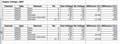
Here's a screen grab of a spreadsheet listing the voltages for my circuit. The supply is at the 185V referenced in the original schematic, but I'm seeing some strangeness...
I have some issues with the 6N23P plate at pin one in both channels now-- it should be 123V and I'm seeing 160V. Also, the cathode voltage at the 12AY7s is a bit low.
I'm still investigating, but I thought I'd post my test results for your review. If anything obvious is sticking out here, please let me know. I'll be checking resistances next.
Kofi
Attachments
- Status
- This old topic is closed. If you want to reopen this topic, contact a moderator using the "Report Post" button.
- Home
- Amplifiers
- Tubes / Valves
- Kofi Annan in: "Cascodin' with Steve Bench's RIAA!"