I still see little reason to get much lower then about 80Hz.It looks like if I can get down to 60Hz semi-anechoic with absorption then I’m “gold”.
My limitation here would be height (assuming it even works-out): like just a little less than 5 feet for my small *room though my preference for tall slim loudspeakers are 2-piece designs, so I think almost 5 feet will be enough for the bass section.
*after both floor & ceiling absorption (8ft high room)
*after both floor & ceiling absorption (8ft high room)
Below Fs of the system, they still follow a very predictable behavior.Reasons could be designing a cardioid, a polar for a back loaded horn, a larger planar loudspeaker. All of which I have worked on.
There is more work than simple sealed and bass reflex enclosures!
Since they basically follow the slope of those systems.
If you would have said big line arrays or any other really big horn systems, I would have found that a good argument.
But they also don't fit on a Klippel system either.
Besides the fact that they are very uncommon.
Well, not for sound reinforcement applications, but that's a whole different game all together.
I am working on two right now. A tall MTM back loaded horn. And a 2.2 meter CBT. Again with a back loaded horn. I have a thing for very dynamic low distortion bass. Too many years sitting near bass drums playing French Horn. Few loudspeakers come even a little close to reproducing percussive bass correctly. Same goes for the large reed stops on a Pipe organ as they are basically percussive in nature as well.If you would have said big line arrays or any other really big horn systems, I would have found that a good argument.
And modeling say a cardioid is one thing, actually figuring out where the best placement for the divers and the null, or what a time delay will produce for you is best measured. Something which I keep toying with trying to get a deeper cardioid effect than the roughly 2 octaves possible, but never really discussed in the adverts.
For my uses I will indeed be having a very close to the ground platform and a taller roughly mid height platform. Otherwise it is not a practical design for me as Erin pointed out in his review. Not an exciting prospect lifting a large expensive loudspeaker onto a platform nearly 4 feet high. I have one client that designs loudspeakers that are in the multiple hundreds of pounds, and that we are doing prototype work for currently. A perfect example of what you cannot do with a Klippel system.My limitation here would be height (assuming it even works-out): like just a little less than 5 feet for my small *room though my preference for tall slim loudspeakers are 2-piece designs, so I think almost 5 feet will be enough for the bass section.
*after both floor & ceiling absorption (8ft high room)
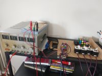
I can control 3 stepper motors via arduino/grbl from octave. The startup ritual is still a bit sketchy.

Next step will be some aluminum profiles, gantries and other small stuff.
I'm interested in design/visions by others. Otherwise I'm just going to build something that moves and find out along the way what works and doesn't.

Next step will be some aluminum profiles, gantries and other small stuff.
I'm interested in design/visions by others. Otherwise I'm just going to build something that moves and find out along the way what works and doesn't.
Well, I am wondering a few things before I post what possibly could help you. Are you thinking aluminum extrusions?I'm interested in design/visions by others. Otherwise I'm just going to build something that moves and find out along the way what works and doesn't.
Since you're in the Netherlands;Yes, I'm thinking 2020 extrusion and other 3D printer parts for my cute little learning platform.
https://www.aluxprofiel.nl/aluminium-profielen
Basically for rotation I think that FEW has the best idea. The slewing bearing with the gear teeth from Hafele. I was going to augment it with the largest reasonably priced slewing bearing so that I had support farther away as I will be needing to measure many sizes of loudspeakers. So a center ring with geared teeth driven via a stepper motor and a gear, and then another ring for further support. I am planning on cutting a sheet of flooring type OSB in half to make two squares for a sturdy base that can still be moved around. And then a mic boom. Bottom swing arm I think will be wood. The rest will be the extrusion idea. Those POM rack teeth that fit within the extrusion slots ScottG showed sold me on the extrusions. Makes this quite simple to have vertical and horizontal movement with modest weight. ( Sadly my idea with the drawer slides while robust, still needs a linear rack or best setup and it is much heavier. ) Those little plates with the POM rollers that fit again within the tracks are the last part of the puzzle.
I'm guessing 1.5 meters for the horizontal boom and 2.3 meters for the vertical boom.
Some cable stays that can be tightened via turn buckle to keep everything tight. Internally if at all possible. I hate messy work.
I'm guessing 1.5 meters for the horizontal boom and 2.3 meters for the vertical boom.
Some cable stays that can be tightened via turn buckle to keep everything tight. Internally if at all possible. I hate messy work.
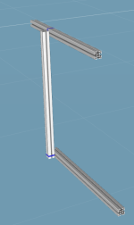
I'm thinking something like this:

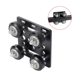
With these:

as connection between the aluminum profiles so they can move with respect to each other. A stepper motor is connected to these gantries by a GT2 belt. Normally the gantry moves, but it might be handy that the profile is moving. One could put all the motors at the rotating table and route the GT2 belt in a complex manner (like CORE XY), but I think I will try to keep it simple and put the motors close to what is being moved at the expense of some extra weight/moment. Low accelerations will keep vibrations under control, hopefully. Speed is important eventually, but first let's simply make it work.

With these:

as connection between the aluminum profiles so they can move with respect to each other. A stepper motor is connected to these gantries by a GT2 belt. Normally the gantry moves, but it might be handy that the profile is moving. One could put all the motors at the rotating table and route the GT2 belt in a complex manner (like CORE XY), but I think I will try to keep it simple and put the motors close to what is being moved at the expense of some extra weight/moment. Low accelerations will keep vibrations under control, hopefully. Speed is important eventually, but first let's simply make it work.
Note 2020 will only go so far before it starts to bend just under its own weight (with a typical lengthwise use).Yes, I'm thinking 2020 extrusion and other 3D printer parts for my cute little learning platform.
Still, if you are just testing-out basic movement then a 2 foot section for the inward/outward axis (and vertical) should be fine. You will also need t-slot gear-rack that slides into the 2020, along with the sliders and connection plates for the motors.
EDIT: I would NOT use a belt; rather direct-drive. IMO a belt might only be truly useful for the vertical when compared to direct (with a counter-weight to offset the weight of the vertical motor + mic./boom and connection plates and slides). Still, up to you (and my guess might prove incorrect).
You are moving a LOT faster than I would have expected; I’ll try to start into this - this weekend, but unfortunately I have other work to complete that takes precedence.

Last edited:
Tom look to see if you can find V Slot extrusion locally. It has been designed just for this purpose and is very reasonably priced. Most of the hobby cnc kits use it for good reason. Look at 2040 extrusions much straighter and stiffer and still light.
Most of maker stores also carry all the linear motion parts and connection fittings too.
Most of maker stores also carry all the linear motion parts and connection fittings too.
Google makes searching outside your geographic area harder than it should be but I could find this
https://vslot-poland.com/V-Slot-Linear-Rail-2040
https://vslot-poland.com/V-Slot-Linear-Rail-2040
My current (manual) mic stand is a six foot tall section of 1 x 2 inch aluminum extrusion. Works great. My suggestion for the diy-Klippel is V-groove 40 mm x 40 mm to accommodate the wheels necessary for translation, and ensure bending won’t be an issue. My 1 x 2 inch vertical extrusion is plenty stiff, but guy wires, as suggested by Mark, would make it even stiffer if it isn’t stiff enough on its own.
I have a quick sketch nearly completed, and I can post it if it clarifies what I’m saying, but in the meantime I‘ll say a large diameter lazy Susan bearing near the floor would provide rotation without cutting so deeply into the speaker height capabilities. A support of whatever height is convenient could be positioned through the hole in the lazy Susan bearing, so speakers of different heights could be accommodated conveniently. Plus the bearings are cheap and don’t require fancy fitting. Casters can support the vertical post so the lazy Susan bearing isn’t trying to support a mass that is a meter away. Sorry if this doesn’t make sense without the sketch. I’ll try to finish that up.
Few
For my uses I will indeed be having a very close to the ground platform and a taller roughly mid height platform. Otherwise it is not a practical design for me as Erin pointed out in his review. Not an exciting prospect lifting a large expensive loudspeaker onto a platform nearly 4 feet high. I have one client that designs loudspeakers that are in the multiple hundreds of pounds, and that we are doing prototype work for currently. A perfect example of what you cannot do with a Klippel system.
Mark, have you seen this? Magico testing their 1,000 lb M9 speaker on the NFS.
Also, my friend is the test engineer at Danley Sound Labs. We chat now and again. He's sent me photos of his setup. He uses a gantry lift like this so they can position their huge PA speakers onto the NFS and measure them.
In fact, for my new house, I'm planning on purchasing an overhead electronic hoist so I don't have to worry about lifting $30k speakers by hand anymore. Cause that's an experience I don't want to have to relive!!
- Erin
Well, now I did!Mark, have you seen this? Magico testing their 1,000 lb M9 speaker on the NFS.
Happily I have a gantry! I built it to move my machine shop tools!
Soon to be machine shop I should say. Long story on that one.
As for heavy lifting loudspeakers, well I'm a big dude, but an older big dude. And I have already lost almost 2 inches of height doing stupid things. So I'm making a variable stand height. And if need be, the Test rig goes to a more reasonable place to test the monsters.
I'm thinking knock down at any rate. Something that can be disassembled with relative ease should the need be.
Erin, make sure you chime in on some of the operational aspects of running the Klippel system that we don't know. Like GUI, and what you like, and don't like about the Klippel GUI. What you would like to see in both the GUI and the program itself but isn't there?
- Home
- Design & Build
- Software Tools
- Klippel Near Field Scanner on a Shoestring