yes. there is still 30v there.
T timwebb Member Joined 2010 2011-10-02 11:12 pm #41 2011-10-02 11:12 pm #41 yes. there is still 30v there. ••• More options Share P Perry Babin Member Joined 2003 bcae1.com 2011-10-02 11:16 pm #42 2011-10-02 11:16 pm #42 Reinstall at least one TIP35 and one TIP36 on each side of the amp and re-check the voltage on the speaker terminals. ••• More options Share T timwebb Member Joined 2010 2011-10-02 11:34 pm #43 2011-10-02 11:34 pm #43 i still got 30+ and 30- ••• More options Share P Perry Babin Member Joined 2003 bcae1.com 2011-10-02 11:37 pm #44 2011-10-02 11:37 pm #44 If you have a module plugged in, remove it and recheck the voltage on the speaker terminals. Do you have BOTH positive and negative regulated voltage on the power supply pins (pins 4 and 7) of the TL071s? ••• More options Share T timwebb Member Joined 2010 2011-10-02 11:55 pm #45 2011-10-02 11:55 pm #45 pin 4. -15.5 pin7. +14.9 ••• More options Share T timwebb Member Joined 2010 2011-10-03 3:28 am #46 2011-10-03 3:28 am #46 i found two shorted drive transistors. i checked them before guess i missed them. im looking them up now. ••• More options Share T timwebb Member Joined 2010 2011-10-03 3:49 am #47 2011-10-03 3:49 am #47 the smd part number is 2q. i got mmbt5087-2n5087 as the part.just checking to be sure. ••• More options Share P Perry Babin Member Joined 2003 bcae1.com 2011-10-03 9:22 am #48 2011-10-03 9:22 am #48 I think that's likely normal. There is an MMBT5087 in the circuit with the base and collector shorted by design. Post the DC voltage on all 8 pins of one of the TL071s. Pin 1: Pin 2: Pin 3: Pin 4: Pin 5: Pin 6: Pin 7: Pin 8: ••• More options Share T timwebb Member Joined 2010 2011-10-04 1:14 am #49 2011-10-04 1:14 am #49 this was taken on the non bridging speaker terminal Pin 1: -15.2 Pin 2: -15.6- Pin 3: -13.5 Pin 4: -15.1 Pin 5: -15.1 Pin 6: 0 Pin 7: 14.8 Pin 8: 0 ••• More options Share P Perry Babin Member Joined 2003 bcae1.com 2011-10-04 7:46 am #50 2011-10-04 7:46 am #50 On that same TL071, there is a resistor connected to pin 3. What is the DC voltage on the end of the resistor NOT connected to pin 3? Place the black probe on one of the non-bridging speaker terminals again. ••• More options Share T timwebb Member Joined 2010 2011-10-05 3:22 am #51 2011-10-05 3:22 am #51 -13.6 ••• More options Share T timwebb Member Joined 2010 2011-10-05 4:02 am #52 2011-10-05 4:02 am #52 i notice that the regulators are getting quite hot Attachments IMAG0114.jpg 677.3 KB · Views: 63 IMAG0115.jpg 630.7 KB · Views: 56 Last edited: 2011-10-05 4:14 am ••• More options Share P Perry Babin Member Joined 2003 bcae1.com 2011-10-05 2:23 pm #53 2011-10-05 2:23 pm #53 The end of the resistor that's NOT connected to pin 3 of the TLO71 should read 0 ohms to the non-bridging speaker terminals. What resistance do you read in your amp (no power applied)? ••• More options Share T timwebb Member Joined 2010 2011-10-06 12:50 am #54 2011-10-06 12:50 am #54 u202 right? Attachments IMAG0108.jpg 500.1 KB · Views: 51 ••• More options Share P Perry Babin Member Joined 2003 bcae1.com 2011-10-06 1:10 am #55 2011-10-06 1:10 am #55 U102 and U202. ••• More options Share T timwebb Member Joined 2010 2011-10-06 1:31 am #56 2011-10-06 1:31 am #56 U202 r210-4mega ohms U102 r110- 0 ohms ••• More options Share P Perry Babin Member Joined 2003 bcae1.com 2011-10-06 1:46 am #57 2011-10-06 1:46 am #57 If the voltage you posted earlier was for U202, post the voltage for U102 now. 4megs is bad. It should be close to 0 ohms. Look for open traces leading away from R210. ••• More options Share T timwebb Member Joined 2010 2011-10-06 2:01 am #58 2011-10-06 2:01 am #58 U202 13v+ U102 0v ••• More options Share P Perry Babin Member Joined 2003 bcae1.com 2011-10-06 2:10 am #59 2011-10-06 2:10 am #59 Post the voltage on all pins of U102. ••• More options Share T timwebb Member Joined 2010 2011-10-06 2:23 am #60 2011-10-06 2:23 am #60 1pin 15.1v 2pin 15.5v 3pin -10.1v 4pin -15.1v 5pin -15.1v 6pin 13.8v 7pin 14.8 8pin 0v ••• More options Share Prev 1 2 3 4 5 Next First Prev 3 of 5 Go to page Go Next Last Show hidden low quality content Status This old topic is closed. If you want to reopen this topic, contact a moderator using the "Report Post" button. Share: Facebook Twitter Reddit Pinterest Tumblr WhatsApp Email Share Link Home General Interest Car Audio kicker xs100 Top Bottom
P Perry Babin Member Joined 2003 bcae1.com 2011-10-02 11:16 pm #42 2011-10-02 11:16 pm #42 Reinstall at least one TIP35 and one TIP36 on each side of the amp and re-check the voltage on the speaker terminals. ••• More options Share T timwebb Member Joined 2010 2011-10-02 11:34 pm #43 2011-10-02 11:34 pm #43 i still got 30+ and 30- ••• More options Share P Perry Babin Member Joined 2003 bcae1.com 2011-10-02 11:37 pm #44 2011-10-02 11:37 pm #44 If you have a module plugged in, remove it and recheck the voltage on the speaker terminals. Do you have BOTH positive and negative regulated voltage on the power supply pins (pins 4 and 7) of the TL071s? ••• More options Share T timwebb Member Joined 2010 2011-10-02 11:55 pm #45 2011-10-02 11:55 pm #45 pin 4. -15.5 pin7. +14.9 ••• More options Share T timwebb Member Joined 2010 2011-10-03 3:28 am #46 2011-10-03 3:28 am #46 i found two shorted drive transistors. i checked them before guess i missed them. im looking them up now. ••• More options Share T timwebb Member Joined 2010 2011-10-03 3:49 am #47 2011-10-03 3:49 am #47 the smd part number is 2q. i got mmbt5087-2n5087 as the part.just checking to be sure. ••• More options Share P Perry Babin Member Joined 2003 bcae1.com 2011-10-03 9:22 am #48 2011-10-03 9:22 am #48 I think that's likely normal. There is an MMBT5087 in the circuit with the base and collector shorted by design. Post the DC voltage on all 8 pins of one of the TL071s. Pin 1: Pin 2: Pin 3: Pin 4: Pin 5: Pin 6: Pin 7: Pin 8: ••• More options Share T timwebb Member Joined 2010 2011-10-04 1:14 am #49 2011-10-04 1:14 am #49 this was taken on the non bridging speaker terminal Pin 1: -15.2 Pin 2: -15.6- Pin 3: -13.5 Pin 4: -15.1 Pin 5: -15.1 Pin 6: 0 Pin 7: 14.8 Pin 8: 0 ••• More options Share P Perry Babin Member Joined 2003 bcae1.com 2011-10-04 7:46 am #50 2011-10-04 7:46 am #50 On that same TL071, there is a resistor connected to pin 3. What is the DC voltage on the end of the resistor NOT connected to pin 3? Place the black probe on one of the non-bridging speaker terminals again. ••• More options Share T timwebb Member Joined 2010 2011-10-05 3:22 am #51 2011-10-05 3:22 am #51 -13.6 ••• More options Share T timwebb Member Joined 2010 2011-10-05 4:02 am #52 2011-10-05 4:02 am #52 i notice that the regulators are getting quite hot Attachments IMAG0114.jpg 677.3 KB · Views: 63 IMAG0115.jpg 630.7 KB · Views: 56 Last edited: 2011-10-05 4:14 am ••• More options Share P Perry Babin Member Joined 2003 bcae1.com 2011-10-05 2:23 pm #53 2011-10-05 2:23 pm #53 The end of the resistor that's NOT connected to pin 3 of the TLO71 should read 0 ohms to the non-bridging speaker terminals. What resistance do you read in your amp (no power applied)? ••• More options Share T timwebb Member Joined 2010 2011-10-06 12:50 am #54 2011-10-06 12:50 am #54 u202 right? Attachments IMAG0108.jpg 500.1 KB · Views: 51 ••• More options Share P Perry Babin Member Joined 2003 bcae1.com 2011-10-06 1:10 am #55 2011-10-06 1:10 am #55 U102 and U202. ••• More options Share T timwebb Member Joined 2010 2011-10-06 1:31 am #56 2011-10-06 1:31 am #56 U202 r210-4mega ohms U102 r110- 0 ohms ••• More options Share P Perry Babin Member Joined 2003 bcae1.com 2011-10-06 1:46 am #57 2011-10-06 1:46 am #57 If the voltage you posted earlier was for U202, post the voltage for U102 now. 4megs is bad. It should be close to 0 ohms. Look for open traces leading away from R210. ••• More options Share T timwebb Member Joined 2010 2011-10-06 2:01 am #58 2011-10-06 2:01 am #58 U202 13v+ U102 0v ••• More options Share P Perry Babin Member Joined 2003 bcae1.com 2011-10-06 2:10 am #59 2011-10-06 2:10 am #59 Post the voltage on all pins of U102. ••• More options Share T timwebb Member Joined 2010 2011-10-06 2:23 am #60 2011-10-06 2:23 am #60 1pin 15.1v 2pin 15.5v 3pin -10.1v 4pin -15.1v 5pin -15.1v 6pin 13.8v 7pin 14.8 8pin 0v ••• More options Share Prev 1 2 3 4 5 Next First Prev 3 of 5 Go to page Go Next Last Show hidden low quality content Status This old topic is closed. If you want to reopen this topic, contact a moderator using the "Report Post" button. Share: Facebook Twitter Reddit Pinterest Tumblr WhatsApp Email Share Link Home General Interest Car Audio kicker xs100 Top Bottom
Reinstall at least one TIP35 and one TIP36 on each side of the amp and re-check the voltage on the speaker terminals.
T timwebb Member Joined 2010 2011-10-02 11:34 pm #43 2011-10-02 11:34 pm #43 i still got 30+ and 30- ••• More options Share P Perry Babin Member Joined 2003 bcae1.com 2011-10-02 11:37 pm #44 2011-10-02 11:37 pm #44 If you have a module plugged in, remove it and recheck the voltage on the speaker terminals. Do you have BOTH positive and negative regulated voltage on the power supply pins (pins 4 and 7) of the TL071s? ••• More options Share T timwebb Member Joined 2010 2011-10-02 11:55 pm #45 2011-10-02 11:55 pm #45 pin 4. -15.5 pin7. +14.9 ••• More options Share T timwebb Member Joined 2010 2011-10-03 3:28 am #46 2011-10-03 3:28 am #46 i found two shorted drive transistors. i checked them before guess i missed them. im looking them up now. ••• More options Share T timwebb Member Joined 2010 2011-10-03 3:49 am #47 2011-10-03 3:49 am #47 the smd part number is 2q. i got mmbt5087-2n5087 as the part.just checking to be sure. ••• More options Share P Perry Babin Member Joined 2003 bcae1.com 2011-10-03 9:22 am #48 2011-10-03 9:22 am #48 I think that's likely normal. There is an MMBT5087 in the circuit with the base and collector shorted by design. Post the DC voltage on all 8 pins of one of the TL071s. Pin 1: Pin 2: Pin 3: Pin 4: Pin 5: Pin 6: Pin 7: Pin 8: ••• More options Share T timwebb Member Joined 2010 2011-10-04 1:14 am #49 2011-10-04 1:14 am #49 this was taken on the non bridging speaker terminal Pin 1: -15.2 Pin 2: -15.6- Pin 3: -13.5 Pin 4: -15.1 Pin 5: -15.1 Pin 6: 0 Pin 7: 14.8 Pin 8: 0 ••• More options Share P Perry Babin Member Joined 2003 bcae1.com 2011-10-04 7:46 am #50 2011-10-04 7:46 am #50 On that same TL071, there is a resistor connected to pin 3. What is the DC voltage on the end of the resistor NOT connected to pin 3? Place the black probe on one of the non-bridging speaker terminals again. ••• More options Share T timwebb Member Joined 2010 2011-10-05 3:22 am #51 2011-10-05 3:22 am #51 -13.6 ••• More options Share T timwebb Member Joined 2010 2011-10-05 4:02 am #52 2011-10-05 4:02 am #52 i notice that the regulators are getting quite hot Attachments IMAG0114.jpg 677.3 KB · Views: 63 IMAG0115.jpg 630.7 KB · Views: 56 Last edited: 2011-10-05 4:14 am ••• More options Share P Perry Babin Member Joined 2003 bcae1.com 2011-10-05 2:23 pm #53 2011-10-05 2:23 pm #53 The end of the resistor that's NOT connected to pin 3 of the TLO71 should read 0 ohms to the non-bridging speaker terminals. What resistance do you read in your amp (no power applied)? ••• More options Share T timwebb Member Joined 2010 2011-10-06 12:50 am #54 2011-10-06 12:50 am #54 u202 right? Attachments IMAG0108.jpg 500.1 KB · Views: 51 ••• More options Share P Perry Babin Member Joined 2003 bcae1.com 2011-10-06 1:10 am #55 2011-10-06 1:10 am #55 U102 and U202. ••• More options Share T timwebb Member Joined 2010 2011-10-06 1:31 am #56 2011-10-06 1:31 am #56 U202 r210-4mega ohms U102 r110- 0 ohms ••• More options Share P Perry Babin Member Joined 2003 bcae1.com 2011-10-06 1:46 am #57 2011-10-06 1:46 am #57 If the voltage you posted earlier was for U202, post the voltage for U102 now. 4megs is bad. It should be close to 0 ohms. Look for open traces leading away from R210. ••• More options Share T timwebb Member Joined 2010 2011-10-06 2:01 am #58 2011-10-06 2:01 am #58 U202 13v+ U102 0v ••• More options Share P Perry Babin Member Joined 2003 bcae1.com 2011-10-06 2:10 am #59 2011-10-06 2:10 am #59 Post the voltage on all pins of U102. ••• More options Share T timwebb Member Joined 2010 2011-10-06 2:23 am #60 2011-10-06 2:23 am #60 1pin 15.1v 2pin 15.5v 3pin -10.1v 4pin -15.1v 5pin -15.1v 6pin 13.8v 7pin 14.8 8pin 0v ••• More options Share Prev 1 2 3 4 5 Next First Prev 3 of 5 Go to page Go Next Last Show hidden low quality content Status This old topic is closed. If you want to reopen this topic, contact a moderator using the "Report Post" button. Share: Facebook Twitter Reddit Pinterest Tumblr WhatsApp Email Share Link Home General Interest Car Audio kicker xs100 Top Bottom
P Perry Babin Member Joined 2003 bcae1.com 2011-10-02 11:37 pm #44 2011-10-02 11:37 pm #44 If you have a module plugged in, remove it and recheck the voltage on the speaker terminals. Do you have BOTH positive and negative regulated voltage on the power supply pins (pins 4 and 7) of the TL071s? ••• More options Share T timwebb Member Joined 2010 2011-10-02 11:55 pm #45 2011-10-02 11:55 pm #45 pin 4. -15.5 pin7. +14.9 ••• More options Share T timwebb Member Joined 2010 2011-10-03 3:28 am #46 2011-10-03 3:28 am #46 i found two shorted drive transistors. i checked them before guess i missed them. im looking them up now. ••• More options Share T timwebb Member Joined 2010 2011-10-03 3:49 am #47 2011-10-03 3:49 am #47 the smd part number is 2q. i got mmbt5087-2n5087 as the part.just checking to be sure. ••• More options Share P Perry Babin Member Joined 2003 bcae1.com 2011-10-03 9:22 am #48 2011-10-03 9:22 am #48 I think that's likely normal. There is an MMBT5087 in the circuit with the base and collector shorted by design. Post the DC voltage on all 8 pins of one of the TL071s. Pin 1: Pin 2: Pin 3: Pin 4: Pin 5: Pin 6: Pin 7: Pin 8: ••• More options Share T timwebb Member Joined 2010 2011-10-04 1:14 am #49 2011-10-04 1:14 am #49 this was taken on the non bridging speaker terminal Pin 1: -15.2 Pin 2: -15.6- Pin 3: -13.5 Pin 4: -15.1 Pin 5: -15.1 Pin 6: 0 Pin 7: 14.8 Pin 8: 0 ••• More options Share P Perry Babin Member Joined 2003 bcae1.com 2011-10-04 7:46 am #50 2011-10-04 7:46 am #50 On that same TL071, there is a resistor connected to pin 3. What is the DC voltage on the end of the resistor NOT connected to pin 3? Place the black probe on one of the non-bridging speaker terminals again. ••• More options Share T timwebb Member Joined 2010 2011-10-05 3:22 am #51 2011-10-05 3:22 am #51 -13.6 ••• More options Share T timwebb Member Joined 2010 2011-10-05 4:02 am #52 2011-10-05 4:02 am #52 i notice that the regulators are getting quite hot Attachments IMAG0114.jpg 677.3 KB · Views: 63 IMAG0115.jpg 630.7 KB · Views: 56 Last edited: 2011-10-05 4:14 am ••• More options Share P Perry Babin Member Joined 2003 bcae1.com 2011-10-05 2:23 pm #53 2011-10-05 2:23 pm #53 The end of the resistor that's NOT connected to pin 3 of the TLO71 should read 0 ohms to the non-bridging speaker terminals. What resistance do you read in your amp (no power applied)? ••• More options Share T timwebb Member Joined 2010 2011-10-06 12:50 am #54 2011-10-06 12:50 am #54 u202 right? Attachments IMAG0108.jpg 500.1 KB · Views: 51 ••• More options Share P Perry Babin Member Joined 2003 bcae1.com 2011-10-06 1:10 am #55 2011-10-06 1:10 am #55 U102 and U202. ••• More options Share T timwebb Member Joined 2010 2011-10-06 1:31 am #56 2011-10-06 1:31 am #56 U202 r210-4mega ohms U102 r110- 0 ohms ••• More options Share P Perry Babin Member Joined 2003 bcae1.com 2011-10-06 1:46 am #57 2011-10-06 1:46 am #57 If the voltage you posted earlier was for U202, post the voltage for U102 now. 4megs is bad. It should be close to 0 ohms. Look for open traces leading away from R210. ••• More options Share T timwebb Member Joined 2010 2011-10-06 2:01 am #58 2011-10-06 2:01 am #58 U202 13v+ U102 0v ••• More options Share P Perry Babin Member Joined 2003 bcae1.com 2011-10-06 2:10 am #59 2011-10-06 2:10 am #59 Post the voltage on all pins of U102. ••• More options Share T timwebb Member Joined 2010 2011-10-06 2:23 am #60 2011-10-06 2:23 am #60 1pin 15.1v 2pin 15.5v 3pin -10.1v 4pin -15.1v 5pin -15.1v 6pin 13.8v 7pin 14.8 8pin 0v ••• More options Share Prev 1 2 3 4 5 Next First Prev 3 of 5 Go to page Go Next Last Show hidden low quality content Status This old topic is closed. If you want to reopen this topic, contact a moderator using the "Report Post" button. Share: Facebook Twitter Reddit Pinterest Tumblr WhatsApp Email Share Link Home General Interest Car Audio kicker xs100 Top Bottom
If you have a module plugged in, remove it and recheck the voltage on the speaker terminals. Do you have BOTH positive and negative regulated voltage on the power supply pins (pins 4 and 7) of the TL071s?
T timwebb Member Joined 2010 2011-10-02 11:55 pm #45 2011-10-02 11:55 pm #45 pin 4. -15.5 pin7. +14.9 ••• More options Share T timwebb Member Joined 2010 2011-10-03 3:28 am #46 2011-10-03 3:28 am #46 i found two shorted drive transistors. i checked them before guess i missed them. im looking them up now. ••• More options Share T timwebb Member Joined 2010 2011-10-03 3:49 am #47 2011-10-03 3:49 am #47 the smd part number is 2q. i got mmbt5087-2n5087 as the part.just checking to be sure. ••• More options Share P Perry Babin Member Joined 2003 bcae1.com 2011-10-03 9:22 am #48 2011-10-03 9:22 am #48 I think that's likely normal. There is an MMBT5087 in the circuit with the base and collector shorted by design. Post the DC voltage on all 8 pins of one of the TL071s. Pin 1: Pin 2: Pin 3: Pin 4: Pin 5: Pin 6: Pin 7: Pin 8: ••• More options Share T timwebb Member Joined 2010 2011-10-04 1:14 am #49 2011-10-04 1:14 am #49 this was taken on the non bridging speaker terminal Pin 1: -15.2 Pin 2: -15.6- Pin 3: -13.5 Pin 4: -15.1 Pin 5: -15.1 Pin 6: 0 Pin 7: 14.8 Pin 8: 0 ••• More options Share P Perry Babin Member Joined 2003 bcae1.com 2011-10-04 7:46 am #50 2011-10-04 7:46 am #50 On that same TL071, there is a resistor connected to pin 3. What is the DC voltage on the end of the resistor NOT connected to pin 3? Place the black probe on one of the non-bridging speaker terminals again. ••• More options Share T timwebb Member Joined 2010 2011-10-05 3:22 am #51 2011-10-05 3:22 am #51 -13.6 ••• More options Share T timwebb Member Joined 2010 2011-10-05 4:02 am #52 2011-10-05 4:02 am #52 i notice that the regulators are getting quite hot Attachments IMAG0114.jpg 677.3 KB · Views: 63 IMAG0115.jpg 630.7 KB · Views: 56 Last edited: 2011-10-05 4:14 am ••• More options Share P Perry Babin Member Joined 2003 bcae1.com 2011-10-05 2:23 pm #53 2011-10-05 2:23 pm #53 The end of the resistor that's NOT connected to pin 3 of the TLO71 should read 0 ohms to the non-bridging speaker terminals. What resistance do you read in your amp (no power applied)? ••• More options Share T timwebb Member Joined 2010 2011-10-06 12:50 am #54 2011-10-06 12:50 am #54 u202 right? Attachments IMAG0108.jpg 500.1 KB · Views: 51 ••• More options Share P Perry Babin Member Joined 2003 bcae1.com 2011-10-06 1:10 am #55 2011-10-06 1:10 am #55 U102 and U202. ••• More options Share T timwebb Member Joined 2010 2011-10-06 1:31 am #56 2011-10-06 1:31 am #56 U202 r210-4mega ohms U102 r110- 0 ohms ••• More options Share P Perry Babin Member Joined 2003 bcae1.com 2011-10-06 1:46 am #57 2011-10-06 1:46 am #57 If the voltage you posted earlier was for U202, post the voltage for U102 now. 4megs is bad. It should be close to 0 ohms. Look for open traces leading away from R210. ••• More options Share T timwebb Member Joined 2010 2011-10-06 2:01 am #58 2011-10-06 2:01 am #58 U202 13v+ U102 0v ••• More options Share P Perry Babin Member Joined 2003 bcae1.com 2011-10-06 2:10 am #59 2011-10-06 2:10 am #59 Post the voltage on all pins of U102. ••• More options Share T timwebb Member Joined 2010 2011-10-06 2:23 am #60 2011-10-06 2:23 am #60 1pin 15.1v 2pin 15.5v 3pin -10.1v 4pin -15.1v 5pin -15.1v 6pin 13.8v 7pin 14.8 8pin 0v ••• More options Share Prev 1 2 3 4 5 Next First Prev 3 of 5 Go to page Go Next Last Show hidden low quality content Status This old topic is closed. If you want to reopen this topic, contact a moderator using the "Report Post" button. Share: Facebook Twitter Reddit Pinterest Tumblr WhatsApp Email Share Link Home General Interest Car Audio kicker xs100 Top Bottom
T timwebb Member Joined 2010 2011-10-03 3:28 am #46 2011-10-03 3:28 am #46 i found two shorted drive transistors. i checked them before guess i missed them. im looking them up now. ••• More options Share T timwebb Member Joined 2010 2011-10-03 3:49 am #47 2011-10-03 3:49 am #47 the smd part number is 2q. i got mmbt5087-2n5087 as the part.just checking to be sure. ••• More options Share P Perry Babin Member Joined 2003 bcae1.com 2011-10-03 9:22 am #48 2011-10-03 9:22 am #48 I think that's likely normal. There is an MMBT5087 in the circuit with the base and collector shorted by design. Post the DC voltage on all 8 pins of one of the TL071s. Pin 1: Pin 2: Pin 3: Pin 4: Pin 5: Pin 6: Pin 7: Pin 8: ••• More options Share T timwebb Member Joined 2010 2011-10-04 1:14 am #49 2011-10-04 1:14 am #49 this was taken on the non bridging speaker terminal Pin 1: -15.2 Pin 2: -15.6- Pin 3: -13.5 Pin 4: -15.1 Pin 5: -15.1 Pin 6: 0 Pin 7: 14.8 Pin 8: 0 ••• More options Share P Perry Babin Member Joined 2003 bcae1.com 2011-10-04 7:46 am #50 2011-10-04 7:46 am #50 On that same TL071, there is a resistor connected to pin 3. What is the DC voltage on the end of the resistor NOT connected to pin 3? Place the black probe on one of the non-bridging speaker terminals again. ••• More options Share T timwebb Member Joined 2010 2011-10-05 3:22 am #51 2011-10-05 3:22 am #51 -13.6 ••• More options Share T timwebb Member Joined 2010 2011-10-05 4:02 am #52 2011-10-05 4:02 am #52 i notice that the regulators are getting quite hot Attachments IMAG0114.jpg 677.3 KB · Views: 63 IMAG0115.jpg 630.7 KB · Views: 56 Last edited: 2011-10-05 4:14 am ••• More options Share P Perry Babin Member Joined 2003 bcae1.com 2011-10-05 2:23 pm #53 2011-10-05 2:23 pm #53 The end of the resistor that's NOT connected to pin 3 of the TLO71 should read 0 ohms to the non-bridging speaker terminals. What resistance do you read in your amp (no power applied)? ••• More options Share T timwebb Member Joined 2010 2011-10-06 12:50 am #54 2011-10-06 12:50 am #54 u202 right? Attachments IMAG0108.jpg 500.1 KB · Views: 51 ••• More options Share P Perry Babin Member Joined 2003 bcae1.com 2011-10-06 1:10 am #55 2011-10-06 1:10 am #55 U102 and U202. ••• More options Share T timwebb Member Joined 2010 2011-10-06 1:31 am #56 2011-10-06 1:31 am #56 U202 r210-4mega ohms U102 r110- 0 ohms ••• More options Share P Perry Babin Member Joined 2003 bcae1.com 2011-10-06 1:46 am #57 2011-10-06 1:46 am #57 If the voltage you posted earlier was for U202, post the voltage for U102 now. 4megs is bad. It should be close to 0 ohms. Look for open traces leading away from R210. ••• More options Share T timwebb Member Joined 2010 2011-10-06 2:01 am #58 2011-10-06 2:01 am #58 U202 13v+ U102 0v ••• More options Share P Perry Babin Member Joined 2003 bcae1.com 2011-10-06 2:10 am #59 2011-10-06 2:10 am #59 Post the voltage on all pins of U102. ••• More options Share T timwebb Member Joined 2010 2011-10-06 2:23 am #60 2011-10-06 2:23 am #60 1pin 15.1v 2pin 15.5v 3pin -10.1v 4pin -15.1v 5pin -15.1v 6pin 13.8v 7pin 14.8 8pin 0v ••• More options Share Prev 1 2 3 4 5 Next First Prev 3 of 5 Go to page Go Next Last Show hidden low quality content Status This old topic is closed. If you want to reopen this topic, contact a moderator using the "Report Post" button. Share: Facebook Twitter Reddit Pinterest Tumblr WhatsApp Email Share Link Home General Interest Car Audio kicker xs100 Top Bottom
i found two shorted drive transistors. i checked them before guess i missed them. im looking them up now.
T timwebb Member Joined 2010 2011-10-03 3:49 am #47 2011-10-03 3:49 am #47 the smd part number is 2q. i got mmbt5087-2n5087 as the part.just checking to be sure. ••• More options Share P Perry Babin Member Joined 2003 bcae1.com 2011-10-03 9:22 am #48 2011-10-03 9:22 am #48 I think that's likely normal. There is an MMBT5087 in the circuit with the base and collector shorted by design. Post the DC voltage on all 8 pins of one of the TL071s. Pin 1: Pin 2: Pin 3: Pin 4: Pin 5: Pin 6: Pin 7: Pin 8: ••• More options Share T timwebb Member Joined 2010 2011-10-04 1:14 am #49 2011-10-04 1:14 am #49 this was taken on the non bridging speaker terminal Pin 1: -15.2 Pin 2: -15.6- Pin 3: -13.5 Pin 4: -15.1 Pin 5: -15.1 Pin 6: 0 Pin 7: 14.8 Pin 8: 0 ••• More options Share P Perry Babin Member Joined 2003 bcae1.com 2011-10-04 7:46 am #50 2011-10-04 7:46 am #50 On that same TL071, there is a resistor connected to pin 3. What is the DC voltage on the end of the resistor NOT connected to pin 3? Place the black probe on one of the non-bridging speaker terminals again. ••• More options Share T timwebb Member Joined 2010 2011-10-05 3:22 am #51 2011-10-05 3:22 am #51 -13.6 ••• More options Share T timwebb Member Joined 2010 2011-10-05 4:02 am #52 2011-10-05 4:02 am #52 i notice that the regulators are getting quite hot Attachments IMAG0114.jpg 677.3 KB · Views: 63 IMAG0115.jpg 630.7 KB · Views: 56 Last edited: 2011-10-05 4:14 am ••• More options Share P Perry Babin Member Joined 2003 bcae1.com 2011-10-05 2:23 pm #53 2011-10-05 2:23 pm #53 The end of the resistor that's NOT connected to pin 3 of the TLO71 should read 0 ohms to the non-bridging speaker terminals. What resistance do you read in your amp (no power applied)? ••• More options Share T timwebb Member Joined 2010 2011-10-06 12:50 am #54 2011-10-06 12:50 am #54 u202 right? Attachments IMAG0108.jpg 500.1 KB · Views: 51 ••• More options Share P Perry Babin Member Joined 2003 bcae1.com 2011-10-06 1:10 am #55 2011-10-06 1:10 am #55 U102 and U202. ••• More options Share T timwebb Member Joined 2010 2011-10-06 1:31 am #56 2011-10-06 1:31 am #56 U202 r210-4mega ohms U102 r110- 0 ohms ••• More options Share P Perry Babin Member Joined 2003 bcae1.com 2011-10-06 1:46 am #57 2011-10-06 1:46 am #57 If the voltage you posted earlier was for U202, post the voltage for U102 now. 4megs is bad. It should be close to 0 ohms. Look for open traces leading away from R210. ••• More options Share T timwebb Member Joined 2010 2011-10-06 2:01 am #58 2011-10-06 2:01 am #58 U202 13v+ U102 0v ••• More options Share P Perry Babin Member Joined 2003 bcae1.com 2011-10-06 2:10 am #59 2011-10-06 2:10 am #59 Post the voltage on all pins of U102. ••• More options Share T timwebb Member Joined 2010 2011-10-06 2:23 am #60 2011-10-06 2:23 am #60 1pin 15.1v 2pin 15.5v 3pin -10.1v 4pin -15.1v 5pin -15.1v 6pin 13.8v 7pin 14.8 8pin 0v ••• More options Share Prev 1 2 3 4 5 Next First Prev 3 of 5 Go to page Go Next Last Show hidden low quality content Status This old topic is closed. If you want to reopen this topic, contact a moderator using the "Report Post" button. Share: Facebook Twitter Reddit Pinterest Tumblr WhatsApp Email Share Link Home General Interest Car Audio kicker xs100 Top Bottom
P Perry Babin Member Joined 2003 bcae1.com 2011-10-03 9:22 am #48 2011-10-03 9:22 am #48 I think that's likely normal. There is an MMBT5087 in the circuit with the base and collector shorted by design. Post the DC voltage on all 8 pins of one of the TL071s. Pin 1: Pin 2: Pin 3: Pin 4: Pin 5: Pin 6: Pin 7: Pin 8: ••• More options Share T timwebb Member Joined 2010 2011-10-04 1:14 am #49 2011-10-04 1:14 am #49 this was taken on the non bridging speaker terminal Pin 1: -15.2 Pin 2: -15.6- Pin 3: -13.5 Pin 4: -15.1 Pin 5: -15.1 Pin 6: 0 Pin 7: 14.8 Pin 8: 0 ••• More options Share P Perry Babin Member Joined 2003 bcae1.com 2011-10-04 7:46 am #50 2011-10-04 7:46 am #50 On that same TL071, there is a resistor connected to pin 3. What is the DC voltage on the end of the resistor NOT connected to pin 3? Place the black probe on one of the non-bridging speaker terminals again. ••• More options Share T timwebb Member Joined 2010 2011-10-05 3:22 am #51 2011-10-05 3:22 am #51 -13.6 ••• More options Share T timwebb Member Joined 2010 2011-10-05 4:02 am #52 2011-10-05 4:02 am #52 i notice that the regulators are getting quite hot Attachments IMAG0114.jpg 677.3 KB · Views: 63 IMAG0115.jpg 630.7 KB · Views: 56 Last edited: 2011-10-05 4:14 am ••• More options Share P Perry Babin Member Joined 2003 bcae1.com 2011-10-05 2:23 pm #53 2011-10-05 2:23 pm #53 The end of the resistor that's NOT connected to pin 3 of the TLO71 should read 0 ohms to the non-bridging speaker terminals. What resistance do you read in your amp (no power applied)? ••• More options Share T timwebb Member Joined 2010 2011-10-06 12:50 am #54 2011-10-06 12:50 am #54 u202 right? Attachments IMAG0108.jpg 500.1 KB · Views: 51 ••• More options Share P Perry Babin Member Joined 2003 bcae1.com 2011-10-06 1:10 am #55 2011-10-06 1:10 am #55 U102 and U202. ••• More options Share T timwebb Member Joined 2010 2011-10-06 1:31 am #56 2011-10-06 1:31 am #56 U202 r210-4mega ohms U102 r110- 0 ohms ••• More options Share P Perry Babin Member Joined 2003 bcae1.com 2011-10-06 1:46 am #57 2011-10-06 1:46 am #57 If the voltage you posted earlier was for U202, post the voltage for U102 now. 4megs is bad. It should be close to 0 ohms. Look for open traces leading away from R210. ••• More options Share T timwebb Member Joined 2010 2011-10-06 2:01 am #58 2011-10-06 2:01 am #58 U202 13v+ U102 0v ••• More options Share P Perry Babin Member Joined 2003 bcae1.com 2011-10-06 2:10 am #59 2011-10-06 2:10 am #59 Post the voltage on all pins of U102. ••• More options Share T timwebb Member Joined 2010 2011-10-06 2:23 am #60 2011-10-06 2:23 am #60 1pin 15.1v 2pin 15.5v 3pin -10.1v 4pin -15.1v 5pin -15.1v 6pin 13.8v 7pin 14.8 8pin 0v ••• More options Share Prev 1 2 3 4 5 Next First Prev 3 of 5 Go to page Go Next Last Show hidden low quality content Status This old topic is closed. If you want to reopen this topic, contact a moderator using the "Report Post" button. Share: Facebook Twitter Reddit Pinterest Tumblr WhatsApp Email Share Link Home General Interest Car Audio kicker xs100 Top Bottom
I think that's likely normal. There is an MMBT5087 in the circuit with the base and collector shorted by design. Post the DC voltage on all 8 pins of one of the TL071s. Pin 1: Pin 2: Pin 3: Pin 4: Pin 5: Pin 6: Pin 7: Pin 8:
T timwebb Member Joined 2010 2011-10-04 1:14 am #49 2011-10-04 1:14 am #49 this was taken on the non bridging speaker terminal Pin 1: -15.2 Pin 2: -15.6- Pin 3: -13.5 Pin 4: -15.1 Pin 5: -15.1 Pin 6: 0 Pin 7: 14.8 Pin 8: 0 ••• More options Share P Perry Babin Member Joined 2003 bcae1.com 2011-10-04 7:46 am #50 2011-10-04 7:46 am #50 On that same TL071, there is a resistor connected to pin 3. What is the DC voltage on the end of the resistor NOT connected to pin 3? Place the black probe on one of the non-bridging speaker terminals again. ••• More options Share T timwebb Member Joined 2010 2011-10-05 3:22 am #51 2011-10-05 3:22 am #51 -13.6 ••• More options Share T timwebb Member Joined 2010 2011-10-05 4:02 am #52 2011-10-05 4:02 am #52 i notice that the regulators are getting quite hot Attachments IMAG0114.jpg 677.3 KB · Views: 63 IMAG0115.jpg 630.7 KB · Views: 56 Last edited: 2011-10-05 4:14 am ••• More options Share P Perry Babin Member Joined 2003 bcae1.com 2011-10-05 2:23 pm #53 2011-10-05 2:23 pm #53 The end of the resistor that's NOT connected to pin 3 of the TLO71 should read 0 ohms to the non-bridging speaker terminals. What resistance do you read in your amp (no power applied)? ••• More options Share T timwebb Member Joined 2010 2011-10-06 12:50 am #54 2011-10-06 12:50 am #54 u202 right? Attachments IMAG0108.jpg 500.1 KB · Views: 51 ••• More options Share P Perry Babin Member Joined 2003 bcae1.com 2011-10-06 1:10 am #55 2011-10-06 1:10 am #55 U102 and U202. ••• More options Share T timwebb Member Joined 2010 2011-10-06 1:31 am #56 2011-10-06 1:31 am #56 U202 r210-4mega ohms U102 r110- 0 ohms ••• More options Share P Perry Babin Member Joined 2003 bcae1.com 2011-10-06 1:46 am #57 2011-10-06 1:46 am #57 If the voltage you posted earlier was for U202, post the voltage for U102 now. 4megs is bad. It should be close to 0 ohms. Look for open traces leading away from R210. ••• More options Share T timwebb Member Joined 2010 2011-10-06 2:01 am #58 2011-10-06 2:01 am #58 U202 13v+ U102 0v ••• More options Share P Perry Babin Member Joined 2003 bcae1.com 2011-10-06 2:10 am #59 2011-10-06 2:10 am #59 Post the voltage on all pins of U102. ••• More options Share T timwebb Member Joined 2010 2011-10-06 2:23 am #60 2011-10-06 2:23 am #60 1pin 15.1v 2pin 15.5v 3pin -10.1v 4pin -15.1v 5pin -15.1v 6pin 13.8v 7pin 14.8 8pin 0v ••• More options Share Prev 1 2 3 4 5 Next First Prev 3 of 5 Go to page Go Next Last Show hidden low quality content Status This old topic is closed. If you want to reopen this topic, contact a moderator using the "Report Post" button. Share: Facebook Twitter Reddit Pinterest Tumblr WhatsApp Email Share Link Home General Interest Car Audio kicker xs100 Top Bottom
this was taken on the non bridging speaker terminal Pin 1: -15.2 Pin 2: -15.6- Pin 3: -13.5 Pin 4: -15.1 Pin 5: -15.1 Pin 6: 0 Pin 7: 14.8 Pin 8: 0
P Perry Babin Member Joined 2003 bcae1.com 2011-10-04 7:46 am #50 2011-10-04 7:46 am #50 On that same TL071, there is a resistor connected to pin 3. What is the DC voltage on the end of the resistor NOT connected to pin 3? Place the black probe on one of the non-bridging speaker terminals again. ••• More options Share T timwebb Member Joined 2010 2011-10-05 3:22 am #51 2011-10-05 3:22 am #51 -13.6 ••• More options Share T timwebb Member Joined 2010 2011-10-05 4:02 am #52 2011-10-05 4:02 am #52 i notice that the regulators are getting quite hot Attachments IMAG0114.jpg 677.3 KB · Views: 63 IMAG0115.jpg 630.7 KB · Views: 56 Last edited: 2011-10-05 4:14 am ••• More options Share P Perry Babin Member Joined 2003 bcae1.com 2011-10-05 2:23 pm #53 2011-10-05 2:23 pm #53 The end of the resistor that's NOT connected to pin 3 of the TLO71 should read 0 ohms to the non-bridging speaker terminals. What resistance do you read in your amp (no power applied)? ••• More options Share T timwebb Member Joined 2010 2011-10-06 12:50 am #54 2011-10-06 12:50 am #54 u202 right? Attachments IMAG0108.jpg 500.1 KB · Views: 51 ••• More options Share P Perry Babin Member Joined 2003 bcae1.com 2011-10-06 1:10 am #55 2011-10-06 1:10 am #55 U102 and U202. ••• More options Share T timwebb Member Joined 2010 2011-10-06 1:31 am #56 2011-10-06 1:31 am #56 U202 r210-4mega ohms U102 r110- 0 ohms ••• More options Share P Perry Babin Member Joined 2003 bcae1.com 2011-10-06 1:46 am #57 2011-10-06 1:46 am #57 If the voltage you posted earlier was for U202, post the voltage for U102 now. 4megs is bad. It should be close to 0 ohms. Look for open traces leading away from R210. ••• More options Share T timwebb Member Joined 2010 2011-10-06 2:01 am #58 2011-10-06 2:01 am #58 U202 13v+ U102 0v ••• More options Share P Perry Babin Member Joined 2003 bcae1.com 2011-10-06 2:10 am #59 2011-10-06 2:10 am #59 Post the voltage on all pins of U102. ••• More options Share T timwebb Member Joined 2010 2011-10-06 2:23 am #60 2011-10-06 2:23 am #60 1pin 15.1v 2pin 15.5v 3pin -10.1v 4pin -15.1v 5pin -15.1v 6pin 13.8v 7pin 14.8 8pin 0v ••• More options Share Prev 1 2 3 4 5 Next First Prev 3 of 5 Go to page Go Next Last Show hidden low quality content Status This old topic is closed. If you want to reopen this topic, contact a moderator using the "Report Post" button. Share: Facebook Twitter Reddit Pinterest Tumblr WhatsApp Email Share Link Home General Interest Car Audio kicker xs100 Top Bottom
On that same TL071, there is a resistor connected to pin 3. What is the DC voltage on the end of the resistor NOT connected to pin 3? Place the black probe on one of the non-bridging speaker terminals again.
T timwebb Member Joined 2010 2011-10-05 3:22 am #51 2011-10-05 3:22 am #51 -13.6 ••• More options Share T timwebb Member Joined 2010 2011-10-05 4:02 am #52 2011-10-05 4:02 am #52 i notice that the regulators are getting quite hot Attachments IMAG0114.jpg 677.3 KB · Views: 63 IMAG0115.jpg 630.7 KB · Views: 56 Last edited: 2011-10-05 4:14 am ••• More options Share P Perry Babin Member Joined 2003 bcae1.com 2011-10-05 2:23 pm #53 2011-10-05 2:23 pm #53 The end of the resistor that's NOT connected to pin 3 of the TLO71 should read 0 ohms to the non-bridging speaker terminals. What resistance do you read in your amp (no power applied)? ••• More options Share T timwebb Member Joined 2010 2011-10-06 12:50 am #54 2011-10-06 12:50 am #54 u202 right? Attachments IMAG0108.jpg 500.1 KB · Views: 51 ••• More options Share P Perry Babin Member Joined 2003 bcae1.com 2011-10-06 1:10 am #55 2011-10-06 1:10 am #55 U102 and U202. ••• More options Share T timwebb Member Joined 2010 2011-10-06 1:31 am #56 2011-10-06 1:31 am #56 U202 r210-4mega ohms U102 r110- 0 ohms ••• More options Share P Perry Babin Member Joined 2003 bcae1.com 2011-10-06 1:46 am #57 2011-10-06 1:46 am #57 If the voltage you posted earlier was for U202, post the voltage for U102 now. 4megs is bad. It should be close to 0 ohms. Look for open traces leading away from R210. ••• More options Share T timwebb Member Joined 2010 2011-10-06 2:01 am #58 2011-10-06 2:01 am #58 U202 13v+ U102 0v ••• More options Share P Perry Babin Member Joined 2003 bcae1.com 2011-10-06 2:10 am #59 2011-10-06 2:10 am #59 Post the voltage on all pins of U102. ••• More options Share T timwebb Member Joined 2010 2011-10-06 2:23 am #60 2011-10-06 2:23 am #60 1pin 15.1v 2pin 15.5v 3pin -10.1v 4pin -15.1v 5pin -15.1v 6pin 13.8v 7pin 14.8 8pin 0v ••• More options Share Prev 1 2 3 4 5 Next First Prev 3 of 5 Go to page Go Next Last Show hidden low quality content Status This old topic is closed. If you want to reopen this topic, contact a moderator using the "Report Post" button. Share: Facebook Twitter Reddit Pinterest Tumblr WhatsApp Email Share Link Home General Interest Car Audio kicker xs100 Top Bottom
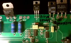
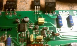
T timwebb Member Joined 2010 2011-10-05 4:02 am #52 2011-10-05 4:02 am #52 i notice that the regulators are getting quite hot Attachments IMAG0114.jpg 677.3 KB · Views: 63 IMAG0115.jpg 630.7 KB · Views: 56 Last edited: 2011-10-05 4:14 am ••• More options Share P Perry Babin Member Joined 2003 bcae1.com 2011-10-05 2:23 pm #53 2011-10-05 2:23 pm #53 The end of the resistor that's NOT connected to pin 3 of the TLO71 should read 0 ohms to the non-bridging speaker terminals. What resistance do you read in your amp (no power applied)? ••• More options Share T timwebb Member Joined 2010 2011-10-06 12:50 am #54 2011-10-06 12:50 am #54 u202 right? Attachments IMAG0108.jpg 500.1 KB · Views: 51 ••• More options Share P Perry Babin Member Joined 2003 bcae1.com 2011-10-06 1:10 am #55 2011-10-06 1:10 am #55 U102 and U202. ••• More options Share T timwebb Member Joined 2010 2011-10-06 1:31 am #56 2011-10-06 1:31 am #56 U202 r210-4mega ohms U102 r110- 0 ohms ••• More options Share P Perry Babin Member Joined 2003 bcae1.com 2011-10-06 1:46 am #57 2011-10-06 1:46 am #57 If the voltage you posted earlier was for U202, post the voltage for U102 now. 4megs is bad. It should be close to 0 ohms. Look for open traces leading away from R210. ••• More options Share T timwebb Member Joined 2010 2011-10-06 2:01 am #58 2011-10-06 2:01 am #58 U202 13v+ U102 0v ••• More options Share P Perry Babin Member Joined 2003 bcae1.com 2011-10-06 2:10 am #59 2011-10-06 2:10 am #59 Post the voltage on all pins of U102. ••• More options Share T timwebb Member Joined 2010 2011-10-06 2:23 am #60 2011-10-06 2:23 am #60 1pin 15.1v 2pin 15.5v 3pin -10.1v 4pin -15.1v 5pin -15.1v 6pin 13.8v 7pin 14.8 8pin 0v ••• More options Share Prev 1 2 3 4 5 Next First Prev 3 of 5 Go to page Go Next Last Show hidden low quality content Status This old topic is closed. If you want to reopen this topic, contact a moderator using the "Report Post" button. Share: Facebook Twitter Reddit Pinterest Tumblr WhatsApp Email Share Link Home General Interest Car Audio kicker xs100 Top Bottom
P Perry Babin Member Joined 2003 bcae1.com 2011-10-05 2:23 pm #53 2011-10-05 2:23 pm #53 The end of the resistor that's NOT connected to pin 3 of the TLO71 should read 0 ohms to the non-bridging speaker terminals. What resistance do you read in your amp (no power applied)? ••• More options Share T timwebb Member Joined 2010 2011-10-06 12:50 am #54 2011-10-06 12:50 am #54 u202 right? Attachments IMAG0108.jpg 500.1 KB · Views: 51 ••• More options Share P Perry Babin Member Joined 2003 bcae1.com 2011-10-06 1:10 am #55 2011-10-06 1:10 am #55 U102 and U202. ••• More options Share T timwebb Member Joined 2010 2011-10-06 1:31 am #56 2011-10-06 1:31 am #56 U202 r210-4mega ohms U102 r110- 0 ohms ••• More options Share P Perry Babin Member Joined 2003 bcae1.com 2011-10-06 1:46 am #57 2011-10-06 1:46 am #57 If the voltage you posted earlier was for U202, post the voltage for U102 now. 4megs is bad. It should be close to 0 ohms. Look for open traces leading away from R210. ••• More options Share T timwebb Member Joined 2010 2011-10-06 2:01 am #58 2011-10-06 2:01 am #58 U202 13v+ U102 0v ••• More options Share P Perry Babin Member Joined 2003 bcae1.com 2011-10-06 2:10 am #59 2011-10-06 2:10 am #59 Post the voltage on all pins of U102. ••• More options Share T timwebb Member Joined 2010 2011-10-06 2:23 am #60 2011-10-06 2:23 am #60 1pin 15.1v 2pin 15.5v 3pin -10.1v 4pin -15.1v 5pin -15.1v 6pin 13.8v 7pin 14.8 8pin 0v ••• More options Share Prev 1 2 3 4 5 Next First Prev 3 of 5 Go to page Go Next Last Show hidden low quality content Status This old topic is closed. If you want to reopen this topic, contact a moderator using the "Report Post" button. Share: Facebook Twitter Reddit Pinterest Tumblr WhatsApp Email Share Link Home General Interest Car Audio kicker xs100
The end of the resistor that's NOT connected to pin 3 of the TLO71 should read 0 ohms to the non-bridging speaker terminals. What resistance do you read in your amp (no power applied)?
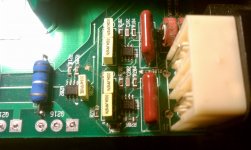
T timwebb Member Joined 2010 2011-10-06 12:50 am #54 2011-10-06 12:50 am #54 u202 right? Attachments IMAG0108.jpg 500.1 KB · Views: 51 ••• More options Share P Perry Babin Member Joined 2003 bcae1.com 2011-10-06 1:10 am #55 2011-10-06 1:10 am #55 U102 and U202. ••• More options Share T timwebb Member Joined 2010 2011-10-06 1:31 am #56 2011-10-06 1:31 am #56 U202 r210-4mega ohms U102 r110- 0 ohms ••• More options Share P Perry Babin Member Joined 2003 bcae1.com 2011-10-06 1:46 am #57 2011-10-06 1:46 am #57 If the voltage you posted earlier was for U202, post the voltage for U102 now. 4megs is bad. It should be close to 0 ohms. Look for open traces leading away from R210. ••• More options Share T timwebb Member Joined 2010 2011-10-06 2:01 am #58 2011-10-06 2:01 am #58 U202 13v+ U102 0v ••• More options Share P Perry Babin Member Joined 2003 bcae1.com 2011-10-06 2:10 am #59 2011-10-06 2:10 am #59 Post the voltage on all pins of U102. ••• More options Share T timwebb Member Joined 2010 2011-10-06 2:23 am #60 2011-10-06 2:23 am #60 1pin 15.1v 2pin 15.5v 3pin -10.1v 4pin -15.1v 5pin -15.1v 6pin 13.8v 7pin 14.8 8pin 0v ••• More options Share Prev 1 2 3 4 5 Next First Prev 3 of 5 Go to page Go Next Last Show hidden low quality content Status This old topic is closed. If you want to reopen this topic, contact a moderator using the "Report Post" button. Share: Facebook Twitter Reddit Pinterest Tumblr WhatsApp Email Share Link Home General Interest Car Audio kicker xs100
P Perry Babin Member Joined 2003 bcae1.com 2011-10-06 1:10 am #55 2011-10-06 1:10 am #55 U102 and U202. ••• More options Share T timwebb Member Joined 2010 2011-10-06 1:31 am #56 2011-10-06 1:31 am #56 U202 r210-4mega ohms U102 r110- 0 ohms ••• More options Share P Perry Babin Member Joined 2003 bcae1.com 2011-10-06 1:46 am #57 2011-10-06 1:46 am #57 If the voltage you posted earlier was for U202, post the voltage for U102 now. 4megs is bad. It should be close to 0 ohms. Look for open traces leading away from R210. ••• More options Share T timwebb Member Joined 2010 2011-10-06 2:01 am #58 2011-10-06 2:01 am #58 U202 13v+ U102 0v ••• More options Share P Perry Babin Member Joined 2003 bcae1.com 2011-10-06 2:10 am #59 2011-10-06 2:10 am #59 Post the voltage on all pins of U102. ••• More options Share T timwebb Member Joined 2010 2011-10-06 2:23 am #60 2011-10-06 2:23 am #60 1pin 15.1v 2pin 15.5v 3pin -10.1v 4pin -15.1v 5pin -15.1v 6pin 13.8v 7pin 14.8 8pin 0v ••• More options Share Prev 1 2 3 4 5 Next First Prev 3 of 5 Go to page Go Next Last Show hidden low quality content Status This old topic is closed. If you want to reopen this topic, contact a moderator using the "Report Post" button. Share: Facebook Twitter Reddit Pinterest Tumblr WhatsApp Email Share Link
T timwebb Member Joined 2010 2011-10-06 1:31 am #56 2011-10-06 1:31 am #56 U202 r210-4mega ohms U102 r110- 0 ohms ••• More options Share P Perry Babin Member Joined 2003 bcae1.com 2011-10-06 1:46 am #57 2011-10-06 1:46 am #57 If the voltage you posted earlier was for U202, post the voltage for U102 now. 4megs is bad. It should be close to 0 ohms. Look for open traces leading away from R210. ••• More options Share T timwebb Member Joined 2010 2011-10-06 2:01 am #58 2011-10-06 2:01 am #58 U202 13v+ U102 0v ••• More options Share P Perry Babin Member Joined 2003 bcae1.com 2011-10-06 2:10 am #59 2011-10-06 2:10 am #59 Post the voltage on all pins of U102. ••• More options Share T timwebb Member Joined 2010 2011-10-06 2:23 am #60 2011-10-06 2:23 am #60 1pin 15.1v 2pin 15.5v 3pin -10.1v 4pin -15.1v 5pin -15.1v 6pin 13.8v 7pin 14.8 8pin 0v ••• More options Share Prev 1 2 3 4 5 Next First Prev 3 of 5 Go to page Go Next Last Show hidden low quality content Status This old topic is closed. If you want to reopen this topic, contact a moderator using the "Report Post" button. Share: Facebook Twitter Reddit Pinterest Tumblr WhatsApp Email Share Link
P Perry Babin Member Joined 2003 bcae1.com 2011-10-06 1:46 am #57 2011-10-06 1:46 am #57 If the voltage you posted earlier was for U202, post the voltage for U102 now. 4megs is bad. It should be close to 0 ohms. Look for open traces leading away from R210. ••• More options Share T timwebb Member Joined 2010 2011-10-06 2:01 am #58 2011-10-06 2:01 am #58 U202 13v+ U102 0v ••• More options Share P Perry Babin Member Joined 2003 bcae1.com 2011-10-06 2:10 am #59 2011-10-06 2:10 am #59 Post the voltage on all pins of U102. ••• More options Share T timwebb Member Joined 2010 2011-10-06 2:23 am #60 2011-10-06 2:23 am #60 1pin 15.1v 2pin 15.5v 3pin -10.1v 4pin -15.1v 5pin -15.1v 6pin 13.8v 7pin 14.8 8pin 0v ••• More options Share Prev 1 2 3 4 5 Next First Prev 3 of 5 Go to page Go Next Last Show hidden low quality content Status This old topic is closed. If you want to reopen this topic, contact a moderator using the "Report Post" button. Share: Facebook Twitter Reddit Pinterest Tumblr WhatsApp Email Share Link
If the voltage you posted earlier was for U202, post the voltage for U102 now. 4megs is bad. It should be close to 0 ohms. Look for open traces leading away from R210.
T timwebb Member Joined 2010 2011-10-06 2:01 am #58 2011-10-06 2:01 am #58 U202 13v+ U102 0v ••• More options Share P Perry Babin Member Joined 2003 bcae1.com 2011-10-06 2:10 am #59 2011-10-06 2:10 am #59 Post the voltage on all pins of U102. ••• More options Share T timwebb Member Joined 2010 2011-10-06 2:23 am #60 2011-10-06 2:23 am #60 1pin 15.1v 2pin 15.5v 3pin -10.1v 4pin -15.1v 5pin -15.1v 6pin 13.8v 7pin 14.8 8pin 0v ••• More options Share Prev 1 2 3 4 5 Next First Prev 3 of 5 Go to page Go Next Last Show hidden low quality content Status This old topic is closed. If you want to reopen this topic, contact a moderator using the "Report Post" button. Share: Facebook Twitter Reddit Pinterest Tumblr WhatsApp Email Share Link
P Perry Babin Member Joined 2003 bcae1.com 2011-10-06 2:10 am #59 2011-10-06 2:10 am #59 Post the voltage on all pins of U102. ••• More options Share T timwebb Member Joined 2010 2011-10-06 2:23 am #60 2011-10-06 2:23 am #60 1pin 15.1v 2pin 15.5v 3pin -10.1v 4pin -15.1v 5pin -15.1v 6pin 13.8v 7pin 14.8 8pin 0v ••• More options Share Prev 1 2 3 4 5 Next First Prev 3 of 5 Go to page Go Next Last Show hidden low quality content Status This old topic is closed. If you want to reopen this topic, contact a moderator using the "Report Post" button.
T timwebb Member Joined 2010 2011-10-06 2:23 am #60 2011-10-06 2:23 am #60 1pin 15.1v 2pin 15.5v 3pin -10.1v 4pin -15.1v 5pin -15.1v 6pin 13.8v 7pin 14.8 8pin 0v ••• More options Share