morning mooly,sarkis.
just pulled Q21 out of circuit, off of the heatsink. here are the new results, with in circuit measurements framed by (*)
C-E = open (open)
E-C = open (.473)
E-B = open (.232)
B-E = .463 (.232)
C-B = open (open)
B-C = .459 (.432)
which begs the question, should i pull Q23? is 21 shagged as well?
thanks guys.
aidan
p.s. T minus 7 days to visit toronto and deliver the amp. GAK!")
just pulled Q21 out of circuit, off of the heatsink. here are the new results, with in circuit measurements framed by (*)
C-E = open (open)
E-C = open (.473)
E-B = open (.232)
B-E = .463 (.232)
C-B = open (open)
B-C = .459 (.432)
which begs the question, should i pull Q23? is 21 shagged as well?
thanks guys.
aidan
p.s. T minus 7 days to visit toronto and deliver the amp. GAK!
For the fun of it
I bought my self a KA 305 and a KA 3500 some couple of years ago for 20 euros both Liked the 3500 most burned outputs though and i thought about restoring it turbo condition in order to give it to my baby daughters room ( she is 2.5 now ... )
So before measuring anything i started boosting capacitors replacing outputs with 1943 5200 drivers with BD139-140 many resistors all of capacitors both signal ang secondary psu upgraded a few others and so on Hardware also like Ultimax RCA plugs cables and so on \
At first step bias was wrong had to modify the all circuit to get usable bias
Then oscillation all over the place , asymmetrical clip , oscillation occurred also during the operation and far worst at clip conditions
all of the above in simple resistive load
Then i second thought my choices about turbo mode and ground level my self to more simple semis and also try to steal suggestions for drivers already existing in teh KA305
This is how i managed to get there
With the same knowledge i worked out also a broken KA 3030 directly installing TTA001 and TTC001 from Toshiba which worked as drop in replacements minus a trimmer i had to add to adjust bias ...no compensation or oscillation issues
Kind regards
Sakis
For the fun of it
I bought my self a KA 305 and a KA 3500 some couple of years ago for 20 euros both Liked the 3500 most burned outputs though and i thought about restoring it turbo condition in order to give it to my baby daughters room ( she is 2.5 now ... )
So before measuring anything i started boosting capacitors replacing outputs with 1943 5200 drivers with BD139-140 many resistors all of capacitors both signal ang secondary psu upgraded a few others and so on Hardware also like Ultimax RCA plugs cables and so on \
At first step bias was wrong had to modify the all circuit to get usable bias
Then oscillation all over the place , asymmetrical clip , oscillation occurred also during the operation and far worst at clip conditions
all of the above in simple resistive load
Then i second thought my choices about turbo mode and ground level my self to more simple semis and also try to steal suggestions for drivers already existing in teh KA305
This is how i managed to get there
With the same knowledge i worked out also a broken KA 3030 directly installing TTA001 and TTC001 from Toshiba which worked as drop in replacements minus a trimmer i had to add to adjust bias ...no compensation or oscillation issues
Kind regards
Sakis
Its can be strange when certain devices fail to perform as you expect but it does happen of course. And its fun sorting them out if you have the time.
I'm hoping this one will go to plan
fingers crossed sakis, nice when seredipity and knowledge get together. you remember those a long long time.
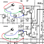
so, i've now pulled Qe23 from the board. this is the device which was shorted to Qe19, emitter to emitter of each.
Qe21 the 2SD588 an NPN with pinout being B-C-E from face, correct?
C-E = open (open)
E-C = open (.473)
E-B = open (.232)
B-E = .463 (.232)
C-B = open (open)
B-C = .459 (.432)
and now
Qe23 the 2SB618, a PNP but with the same pinout of B-C-E. is this common in SS, pnp and npn having same pinout?
Qe23
C-E = open (.512)
E-C = open (open)
E-B = .503 (open)
B-E = open (.231)
C-B = .496 (.458)
B-C = open (open)
Q17 reads
C-E = open
E-C = .562
E-B = .562
B-E = open
C-B = open
B-C = .535
Q19 reads
C-E = .004
E-C = .004
E-B = .537
B-E = open
C-B = open
B-C = .535
okay, SWMBO is beckoning from upstairs that i'm late for leaving for work. oh, the drudgery.
later,
and again much appreciation,
aidan
edit: the parenthesis indicate the readings while the transistors were in circuit. the Qe17 and Qe19 figures were taken out of circuit from the start.
Last edited:
hi guys. well, christmas came early. received two sets of transistors today, two drivers and two finals for each channel.
currently, the 4 transistors for the right channel are removed. not sure how you experts would have me proceed. had a very very long day today. i'll be up, as usual, with the birds tomorrow morn, and will check in here then.
thanks mooly, sakis. you guys have been great!
aidan
currently, the 4 transistors for the right channel are removed. not sure how you experts would have me proceed. had a very very long day today. i'll be up, as usual, with the birds tomorrow morn, and will check in here then.
thanks mooly, sakis. you guys have been great!
aidan
OK. This is how it should end up. We were saying the outputs were OK I think at this point.
Familiarise yourself with the pinouts.
Remember to turn the bias preset on both channels so that it has maximum resistance (so its like a 1k resistor)
Set the amp up with a bulb tester and your variac but don't switch on.
(I'll be back later this morning... 9 am here)
Familiarise yourself with the pinouts.
Remember to turn the bias preset on both channels so that it has maximum resistance (so its like a 1k resistor)
Set the amp up with a bulb tester and your variac but don't switch on.
(I'll be back later this morning... 9 am here)
Attachments
well g'day sir! either way is good for me (original outputs, or the tip41c/42c's). whichever you feel would be the most prudent avenue. i was thinking i'd re-install the originals, as (hopefully) this would preclude me having to install the new devices on to the unscathed channel. sound right?
would one be able to hear the difference between channels if each channel had a different set of drivers and outputs? if so, would it be a notable difference between the two?
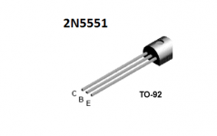
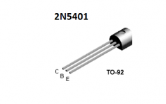
alright then. i'm off to the bench to install the 2N5401 and the 2N5551 drivers. i'll report back once installed, and await further instructions. :-S
aidan
would one be able to hear the difference between channels if each channel had a different set of drivers and outputs? if so, would it be a notable difference between the two?
alright then. i'm off to the bench to install the 2N5401 and the 2N5551 drivers. i'll report back once installed, and await further instructions. :-S
aidan
Last edited:
So we go with the originals for now.
So check list.
1/ Be 100% certain the new devices are fitted correctly.
2/ Bias presets set as mentioned earlier.
3/ Bulb test and variac in place.
4/ Make sure the output devices are correctly secured and insulated with the washers.
No speakers to be connected yet, just your meter as required.
Make sure the variac is set to zero volts and switch on.
4/ Bring the voltage up slowly and the bulb should stay out (or very dim). That's the first step. It would be useful for you to monitor the DC supply voltage by measuring between the two rails. So you would see around 80 volts dc.
Beware that many variacs can give more than the input voltage when on full so don't go over the rated mains voltage.
If all that is OK then we do a couple of basic tests and measurements.
aaarrrgggghhhhh!
oh well, in for a penny, in for a pound.
thanks very much for the lead, though. guys at my local shop told me no way to get them. a scolding is in order.
aidan
Or my popular supplier.
Cricklewood Electronics - CCTV. CCTV Equipment. CCTV Systems. Digital CCTV Cameras
Cricklewood Electronics - CCTV. CCTV Equipment. CCTV Systems. Digital CCTV Cameras
So we go with the originals for now.
So check list.
1/ Be 100% certain the new devices are fitted correctly.
ok, will do. now, i of course noticed that the pinouts are different on the new drivers than on the old (haven't even looked at the new finals yet). does it matter how i bend or manipulate the legs to get them to their correct holes? avoiding any shorts, of course. on many of my amateur radios, such as the yaesu ft-1000mp, one must be careful when installing replacement transistors, with yaseu supplying a diagram showing the correct angle to bend the leg(s), this might just apply to rf, i guess. i really am a noob when it comes to SS.
2/ Bias presets set as mentioned earlier.
roger.
3/ Bulb test and variac in place.
affirmative.
4/ Make sure the output devices are correctly secured and insulated with the washers.
yup. looks like the mica insulators stayed with the heatsink. this okay? should i add new heat transfer compound?
No speakers to be connected yet, just your meter as required.
okay. favourite meter, jackson 709 tele-volter. i have many other vtvms (hp 410b, b&k, heath, eico etc) but this is my go-to meter. HUGE face and needle, easy on my old eyes.
Make sure the variac is set to zero volts and switch on.
okay. this is pending.
4/ Bring the voltage up slowly and the bulb should stay out (or very dim). That's the first step. It would be useful for you to monitor the DC supply voltage by measuring between the two rails. So you would see around 80 volts dc.
newbie question. when you say rails, do you mean the B+ voltage, the rectified voltage after it leaves the power supply? sorry if this sounds dumb.
Beware that many variacs can give more than the input voltage when on full so don't go over the rated mains voltage.
agreed. mine goes to 140V. has three simpson meters. vac, 0-1amp, and 0-10amps. i'll be on the 1 amp setting, and will monitor the current closely.
If all that is OK then we do a couple of basic tests and measurements.
okay. just have a couple of duties to perform for swmbo, and i'll be back in a couple of hours.
thanks mooly, for the help so far.
katieanddad, than you for the link. i'll take a peek later.
aidan
There's no problem with bending the leads other than mechanical issues. Try to keep any bends as gentle curves so that the wire is not stressed and try not to bend directly where the lead exits the package. It is RF work and tuned circuits where things get critical. No such issues here.
A bit of new heatsink compound would do no harm.
The total rail voltage is just from collector to collector of the output transistors. So red lead on the +39 volt rail and black lead on the -39 volt rail. It is just the total rectified voltage.
A bit of new heatsink compound would do no harm.
The total rail voltage is just from collector to collector of the output transistors. So red lead on the +39 volt rail and black lead on the -39 volt rail. It is just the total rectified voltage.
- Status
- This old topic is closed. If you want to reopen this topic, contact a moderator using the "Report Post" button.
- Home
- Amplifiers
- Solid State
- Kenwood KA-3500 and my blooper