I also think the X15 design would be ideal for some experimentation. I am behind on too many things to approach it now. I may list my original design K12 w/guitar speaker on cragslist to see if I get any interest. If it moves that might give me some hope that I could then move an X15 after playing a bit with it.
One could try a build with battens glued in with paper inserted between the batten and the cab. That way the battens could be permanent or easily removed with a chisel to try another configuration. The size of the X15 would be easy to work with inside. I don't like the appearance of the K-tube but if tube, reflector and baffle were done in matte black it would all but disappear.
One could try a build with battens glued in with paper inserted between the batten and the cab. That way the battens could be permanent or easily removed with a chisel to try another configuration. The size of the X15 would be easy to work with inside. I don't like the appearance of the K-tube but if tube, reflector and baffle were done in matte black it would all but disappear.
Last edited:
matte black and a grille cloth would hide things. Karlson's X15 always had cloth and a good idea to preserve the driver and block out destructive pests such as mice.
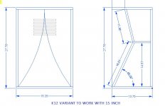
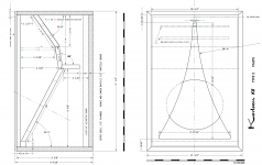
TB46's. sketch of X15 size built like a K12 might play smoother than Karlson's cabinet (?) A K-tube could be added once vents are put towards each side. Remember with ~99dB 15 inch woofers that X15 size will have about the same low end as K12, with a half space rolloff below 80-90Hz. so a subwoofer would help. I like the 1956 Karlson split shelf boards as those provide a good brace for the back and baffle/upper panel boards.
I've always thought a rough test coupler with hinged baffle might be interesting - seal it with duct tape at whatever position is being tested. That would require having a movable reflector and shims.
I just about bet a naked K-tube's aesthetics and public perception thereof with regards to sales is the reason Wolf von Langa did not
go ahead with commercial K-tube topped speakers.
Attachments
Last edited:
 . (listen to that HiFi Workbench show and one will know what I mean
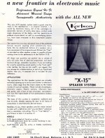
Speakers are addictive and although I have no need for more speakers I can't stop looking. Karlsons especially pique my interest, I think we have yet to really understand what is happening with them and tend to treat them as conventional cabs with a lens in front. I tend to read other threads and contemplate how designs could be contorted to include a Karlson front chamber for coupling the rear chamber The reason I like them is the efficiency, the ability to reduce cone excursion and of course the K aperture which invites conversation.
Although John Karlson did let his antenna design work trickle over into audio there is considerable difference in audio and electromagnetic wave propagation. Consider that microphone design differs considerably from speaker design whereas the following applies to antennas.
Reciprocity states that the receive and transmit properties of an antenna are identical. Hence, antennas do not have distinct transmit and receive radiation patterns - if you know the radiation pattern in the transmit mode then you also know the pattern in the receive mode.
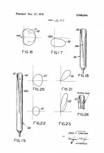
Karlson's patent US3540544 has illustrations for "K-tube" microphones. I'd think the tube resonance would have to be RQ-ed out for that to work (?)
When discussimg John Karlson's work for the 1964 NYC World's Fair, the late Martin Poppe ("The K-coupler") said John had some little Rocket type as Robert Moses intercom mics and that in a way, those were an abstract representation of the "Twin Tower" project.
When discussimg John Karlson's work for the 1964 NYC World's Fair, the late Martin Poppe ("The K-coupler") said John had some little Rocket type as Robert Moses intercom mics and that in a way, those were an abstract representation of the "Twin Tower" project.
Attachments
does that put the vent "external" and "above" the front coupler ? - If so that may have been the way Acoustic Reality's K-home theater subwoofer was done (??? - the picture back in the day at Ulfman's site was vague and description "sekretive" but think the vent was external rather than series and placed above the front chamber)

Last edited:
Karlson's later K8 kit was somewhat different vs my factory assembled K8.
Which do you think would play "smoothest" ? - they could perform somewhat different (???)
Also, going by ray tracing such as Karlson did, which one would do best on
getting bounced waves out through the aperture ?
Which do you think would play "smoothest" ? - they could perform somewhat different (???)
Also, going by ray tracing such as Karlson did, which one would do best on
getting bounced waves out through the aperture ?
Attachments
Last edited:
Interesting, both have the port firing at an angle into the front chamber. I wonder how a tube from lower into upper rear chamber (as in Delsol) would affect performance?Karlson's later K8 kit was somewhat different vs my factory assembled K8.
Which do you think would play "smoothest" ? - they could perform somewhat different (???)
Also, going by ray tracing such as Karlson did, which one would do best on
getting bounced waves out through the aperture ?
Did John or Wayne ever take any chamber measurements to see how the front affected the rear chambers or just a trial and error of all three chambers coupled together. It's obviously a three chamber design that can't be fully analyzed as chambers in isolation.
Last edited:
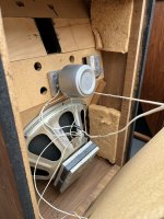
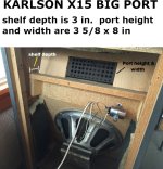
I have a K8 stored in the garage that was scaled from the original K12 design. Come warm weather I think I will modify the rear shelf to separate the rear chambers with a tube projecting into the upper chamber. Then I can easily experiment with different tube lengths. I wonder what tube diameter I should use? I may have to use rectangular as I am restricted to whatever as built (?) clearance is.
Again no test equipment and I haven't found a good SA app for my chromebook yet.
Again no test equipment and I haven't found a good SA app for my chromebook yet.
Karlson appeared to use just a cap (4uF IIRC) with my X15 K-tube's compression driver, but that could be brutal in some cases. 2nd or 3rd (and higher) order highpass would be safer as the little tubes have little to no gain on their low end compared to horn.
A "K8" scaled from K12 could play pretty smooth as that's the way Weltersys's Dad made a pair.
A "K8" scaled from K12 could play pretty smooth as that's the way Weltersys's Dad made a pair.
Wayne Green was not happy with the K experience, being booted from the company and did not discuss things. Martin Poppe may have known but passed away. That probably would only leave Alan Weiss (IF still living) as one who worked with John Karlson.
Poppe said John would listen for problems. Karlson's 1961 letter to Poppe indicates K8 was the precursor of the X15 front chamber profile.
Akabak3, with an experienced user , being adjusted for real world speaker cabinet materials, should allow analysis of front chamber shape and aperture variations with a fixed rear chamber. (or two as many choked K have).
It took some international nudging from the US - to Czech Republic to Greece to get the little taste of what Akabak3 might do with the difficult Karlson arrangement.
Attachments
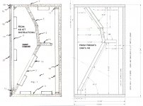
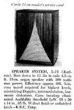
Karlson;s X15 system was introduced late 1965 - a time when stereosound via lp was getting to be the norm. At 28" x 19.25" x ~14" X15 was around 57% the bulk of K15 (K15 wasdeveloped in the summer of 1951) and as a consequence, had a LF rolloff about a half octave higher. X15's bulk was only 1 cubic foot more than K1 and could be an excellent choice. in a system with a subwoofer. X15 being a 2-way factory loaded system had Karlson's open end waveguide slotted-pipe tweeter and hat wored (and still works quite well.
One feature of all Karlson enclosures is "controlled ring time" with the intent of providing greater realism and enhancement of "weak transients"
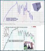
There was a time in the early 1980's where at least four companies were producing an X15 size K-coupler.. Acoustic Control's 115BK measure very smooth even without any damping material and could be a substitute for midbass horn altough needs more
power input.
The earliest X15 used a wood mini-klam with 3 inch cone tweeter- sometime later tha was replaced with the slotted pipe. waveguide. It used a bass guitar CTS 15" woofer.
I think it could be built with a simple upper panel like a K12 and sound pretty good - but DIY member Suntiger likes to use curved reflectors.
One feature of all Karlson enclosures is "controlled ring time" with the intent of providing greater realism and enhancement of "weak transients"
There was a time in the early 1980's where at least four companies were producing an X15 size K-coupler.. Acoustic Control's 115BK measure very smooth even without any damping material and could be a substitute for midbass horn altough needs more
power input.
The earliest X15 used a wood mini-klam with 3 inch cone tweeter- sometime later tha was replaced with the slotted pipe. waveguide. It used a bass guitar CTS 15" woofer.
I think it could be built with a simple upper panel like a K12 and sound pretty good - but DIY member Suntiger likes to use curved reflectors.
Attachments
- Home
- Loudspeakers
- Full Range
- Karlson's "X15" A New Frontier in the Perfect Size