here's a nice 3D model of the Cetec-Gauss K18
https://3dwarehouse.sketchup.com/model/u1bc18499-8365-42ef-9e03-0384f5434a60/Gauss-5181
https://3dwarehouse.sketchup.com/model/u1bc18499-8365-42ef-9e03-0384f5434a60/Gauss-5181
ka3 compared to ka2 should tune the front chamber lower as there's more air mass in the upper half of the chamber.
These are good questions and call for test-boxes whose parts can be easily removed and changed. With such test box, even a couple layers of corrugated cardboard would be useful for the upper panel to answer those questions which otherwise might need AutoCad-Fusion 360 and Akabak3.
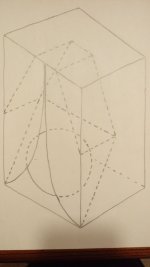
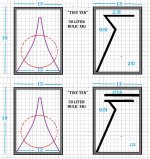
Karlson's final "Acoustic Transducers" patent 3540544 dealt with claims of inprovements by using curved reflectors Fig.6 and Fig.8.
Fig.6 was incorporated into Karlson's "X15" speaker system as a 3 panel quarter ellipse section. I believe it may be a good approach - if done favorably.
I would also suggest curving (perhaps with auto body filler) where the speaker baffle meets the sidewalls.
https://patents.google.com/patent/US3540544A/en
These are good questions and call for test-boxes whose parts can be easily removed and changed. With such test box, even a couple layers of corrugated cardboard would be useful for the upper panel to answer those questions which otherwise might need AutoCad-Fusion 360 and Akabak3.
Karlson's final "Acoustic Transducers" patent 3540544 dealt with claims of inprovements by using curved reflectors Fig.6 and Fig.8.
Fig.6 was incorporated into Karlson's "X15" speaker system as a 3 panel quarter ellipse section. I believe it may be a good approach - if done favorably.
I would also suggest curving (perhaps with auto body filler) where the speaker baffle meets the sidewalls.
https://patents.google.com/patent/US3540544A/en
Attachments
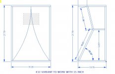
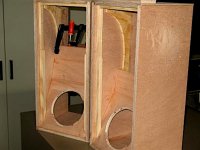
with regards to front chamber shape, there have been many "Dutch K12"built and those have a port panel fully parallel to the wings.
Also, RCA-Fan (Bill Woods) made an X15 size K-coupler with a perpendicular upper panel and about a 2" gap at the top for the port - it made a pretty good graph with a JBL 2226.
https://www.diyaudio.com/community/threads/the-dutch-karlson-12.313227/
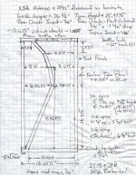
FWIW I would consider building an X15 size K-coupler like the 2nd K12 suggested by TB46 below. It would be one cubic foot larger than a K12 - similar LF cutoff but less excursion due to a 15" speaker's cone area vs that of a 12" speaker.
I don't know about the distributed vent. Having a removable port board would allow lots of experimentation.
Also, RCA-Fan (Bill Woods) made an X15 size K-coupler with a perpendicular upper panel and about a 2" gap at the top for the port - it made a pretty good graph with a JBL 2226.
https://www.diyaudio.com/community/threads/the-dutch-karlson-12.313227/
FWIW I would consider building an X15 size K-coupler like the 2nd K12 suggested by TB46 below. It would be one cubic foot larger than a K12 - similar LF cutoff but less excursion due to a 15" speaker's cone area vs that of a 12" speaker.
I don't know about the distributed vent. Having a removable port board would allow lots of experimentation.
Attachments

Hello .
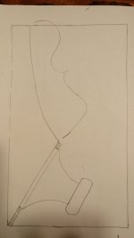
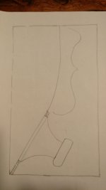
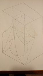
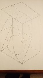
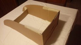
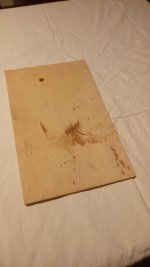
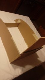
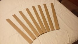
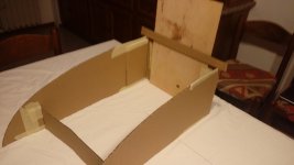
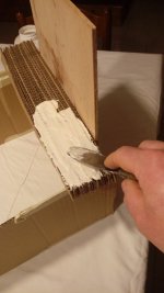
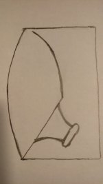
to create curved surfaces I propose this system.
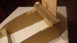
it is a question of creating a mold made up of two parallel sides that have the same curve on which many strips (perpendicular to the two curves and vertical) of suitable thickness are placed.
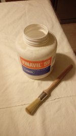
the strips must be glued together, perhaps there are instant glues for wood on the market, bostik for example could be fine.
once the curve is finished the surface is not smooth but made of steps, to eliminate them you can use a modeling paste called DAS that children usually use. once hardened it can be sanded with sandpaper.
I used cardboard because it is for demonstration purposes only but you have to use wood. the less thickness the strips have, the more their number increases, I would say that a good compromise is that of 5mm but it can be increased to 10mm.
I used a few strips because their thickness is small, in reality to make the whole curve needed many more
to create curved surfaces I propose this system.
it is a question of creating a mold made up of two parallel sides that have the same curve on which many strips (perpendicular to the two curves and vertical) of suitable thickness are placed.
the strips must be glued together, perhaps there are instant glues for wood on the market, bostik for example could be fine.
once the curve is finished the surface is not smooth but made of steps, to eliminate them you can use a modeling paste called DAS that children usually use. once hardened it can be sanded with sandpaper.
I used cardboard because it is for demonstration purposes only but you have to use wood. the less thickness the strips have, the more their number increases, I would say that a good compromise is that of 5mm but it can be increased to 10mm.
I used a few strips because their thickness is small, in reality to make the whole curve needed many more
Attachments

hi arivel
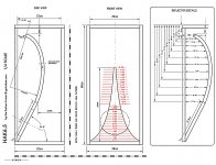
that's a beautiful illustration of a way to make a curved reflector. Diyaudio member "AmadeusMozart" used similar for his SK6.5 project which was based on an 8 inch K-coupler by Carl Neuser.
Where do we want our curved reflector's focus point? I assume its either "at" or a bit"outside" the aperture.
How does one calculate the focus of the arc?
Attachments
Last edited:
A K-Tube with two slots provides symmetrical dispersion - and I personally preferred it to the single slot version. You can print your own and try it out. https://www.diyaudio.com/community/...ompression-drivers.344571/page-4#post-6179069
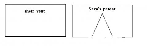
what do you think of "squat aspect" K-style cabinets? Incorporating a smoothing stub may be of value.
If the cavity formed by a shelf vent is causing a suck-out then perhaps Neo's patent could help.
If the cavity formed by a shelf vent is causing a suck-out then perhaps Neo's patent could help.
Attachments
Last edited:
"Now" would be a good time to gather up a list of recommended drivers and driver type in general for Karlson's originals and variant such as GregB's "Karlsonator" and XRK91's "XKi"
Heritage Karlson cabinets were sold empty with coaxial and fullrange drivers in mind starting in 1952. K12 was added in the fall of 1954 and K8 the fall of 1955. As time passed to the point stereo sales were outpacing mono, Karlson introduced the little "X15" two-way system - first with a mini klam 3" paper cone tweeter then a slotted pipe with a compression driver. As X15 was about 5% the bulk of K15, its low frequency cutoff was about a half octave higher than that of K15.
FWIW here's some ramblings
Attachments
- really don't know with regards to motional feedback. One builder has used Leach EQ (like Linkwitz's "transform"). That could be interesting with a sealed back chamber Karlson type. It corrects for 12dB slope so can't fully EQ 4th order low frequency rolloffs.
Subjectively. there is little wrong with the original "K15" design when braced properly and used with coaxial 15 inch speakers similar in characteristics to those of its day. (not too heavy - decent motor strength).
K15 (and K12) should be used as a control when building new "Karlson" enclosure.
Horns may be used on top of K15/X15/K12 etc. and of course can present more presence that coaxial type.
To eliminate the front shelf in a 15" K-coupler, I think it could be of benefit to make the front chamber a few inches less deep.
"De-Q-ing" holes may be used in the reflector panel. It could be interesting to have the reflector panel removable to evaluate different venting schemes as IG81 did with his "TK6".
I would also subjectively evaluate the rear lowpass shelf's effects to hear how it effects bass transients as the gap area is varied. Some of Karlson's designs used a relatively tight gap to the back panel of only ~0.2X Sd.

- Home
- Loudspeakers
- Full Range
- Karlson