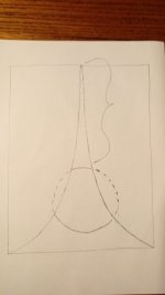
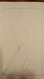
which one did you mean? fig1 or fig2?I would start with a smaller back slot,
Attachments
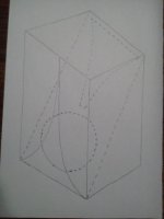
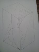
fig 2which one did you mean? fig1 or fig2?
arivel,
I had a sketch of something similar many years ago but promptly forgot about is. I don`t think the internal K-slot would be of any benefit versus any other opening/vent of similar dimension.
IMO, the angle of the speaker baffle should be set to a desired horizontal diffraction target, IOW to where the aperture intercepts the on-axis radiation of the driver. It won`t matter much for lower frequencies, where a square or circular opening would do just as well, but if using a fullrange, coaxial or high-crossed midbass, the tighter the aperture at intercept, the wider the horizontal pattern. I would probably recommend a slightly steeper baffle angle for the classic designs like K15 and K12, around 20-25 degrees from vertical.
Think also of the direct frequencies going from near the floor (position of the driver) up to your listening position.arivel,
I had a sketch of something similar many years ago but promptly forgot about is. I don`t think the internal K-slot would be of any benefit versus any other opening/vent of similar dimension.
IMO, the angle of the speaker baffle should be set to a desired horizontal diffraction target, IOW to where the aperture intercepts the on-axis radiation of the driver. It won`t matter much for lower frequencies, where a square or circular opening would do just as well, but if using a fullrange, coaxial or high-crossed midbass, the tighter the aperture at intercept, the wider the horizontal pattern. I would probably recommend a slightly steeper baffle angle for the classic designs like K15 and K12, around 20-25 degrees from vertical.
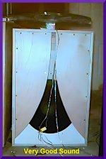
Here's a little "K18" built something like Karlson's 2nd K12 with ~23 degrees baffle tilt, a fowards 10 degree tilt to its port panel. The port panel had two 4.5" x 4.5" square ports. Between those was a hole to mount a K-tube.
If those wings were swiveled inwards at the top for a 5/8" starting gap, sound quality was "constricted" opening to 1.2" gave very good sound quality.
Its obvious there could be many combinations of gap width - wing taper type which could give good result. One set of wings swiveled will let you hear some changes which do not show in measurements.
Also, with my 18 inch speaker, it was fine to have aperture width in the vicinity of the speaker less than that of the usual rule of visually intercepting the cone's surround.
K-wizard Carl Neuser spoke of evaluating a number of apertures -radial arc,"trax 60", exponential, etc.
Acoustic Control's 115BK is a very good little X15 sized K-coupler and could be used with 80Hz crossover to subwoofer.
K15 with appropriate drivers is excellent.
It would be nice for IG81 and other's to formulate a K-recipe strategy for new K-couplers. Maybe TK6 will illuminate some areas to konsider.
Attachments
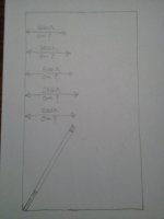
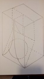
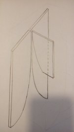
I did not understand if we are talking about the same thing so I am attaching images. for obvious reasons I could not draw all frequenciesarivel,
I had a sketch of something similar many years ago but promptly forgot about is. I don`t think the internal K-slot would be of any benefit versus any other opening/vent of similar dimension.
IMO, the angle of the speaker baffle should be set to a desired horizontal diffraction target, IOW to where the aperture intercepts the on-axis radiation of the driver. It won`t matter much for lower frequencies, where a square or circular opening would do just as well, but if using a fullrange, coaxial or high-crossed midbass, the tighter the aperture at intercept, the wider the horizontal pattern. I would probably recommend a slightly steeper baffle angle for the classic designs like K15 and K12, around 20-25 degrees from vertical.
Attachments
arivel,
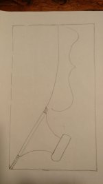
I was talking of the sketch of yours with the internal K-slot, but I also had a similar slot analysis on the defunct Gainclone Karlson forum. The aperture will diffract up to certain frequencies with varying width of course, but I forget what was my exact point back then, though I likely was pretty flawed.")
IMO, the aperture area is the dominant metric, with its starting gap having significant weight towards front chamber tuning. The shape cleverly allows a good amount of direct-radiation from the driver to escape while keeping the tuning from being too low or high.
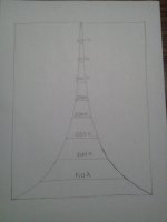
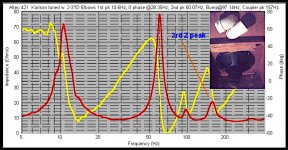
The below graph demonstrates blocking the slot apex on my TK6 in two steps, perhaps ~3-4" each time.
Red = unblocked
Green = ~3" blocked
Blue = ~6" blocked

I was talking of the sketch of yours with the internal K-slot, but I also had a similar slot analysis on the defunct Gainclone Karlson forum. The aperture will diffract up to certain frequencies with varying width of course, but I forget what was my exact point back then, though I likely was pretty flawed.
IMO, the aperture area is the dominant metric, with its starting gap having significant weight towards front chamber tuning. The shape cleverly allows a good amount of direct-radiation from the driver to escape while keeping the tuning from being too low or high.
The below graph demonstrates blocking the slot apex on my TK6 in two steps, perhaps ~3-4" each time.
Red = unblocked
Green = ~3" blocked
Blue = ~6" blocked
see post 243has anyone tried to use a portion of the curve of the front vertical blinds for the interior as well?
K15 has a back chamber volume of around 105 liters , and a system tuning of around 48Hz. That pretty much sets its low frequency cutoff. K15 has been tuned lower by John Tucker for subwoofer use in the Exemplar project where tuning is around 30Hz and boost applied at fb. K15 used that way makes an excellent subwoofer with Altec 15" speakers..
Attachments
If used for more than low-bass, the tuning of the rear chamber should not be too far below that of the front chamber, or risk having a dip in response in the area where the Karlson excels most. The proportions of classic "kouplers" sort of force a higher tuning frequency, in large part because of how speakers were designed in those days. If you tune low with fullrange use in mind, you have to pull-down the front chamber gain to the level a standard reflex would yield yet are still left with response anomalies above this, so no real benefit IMO.
I suppose I could see this affecting the lateral standing-wave, but since I believe the cavity resonance is dominant, I'm not sure how much this would help, although it'd be very easy to implement for a quick test. I'm on other projects for now, but it could be fun to try when I get back on my TK6.
FWIW here's some musings on K15 from an older forum
Gaston comments
Re: Dan Shanefield on the Karlson
« Reply #5 on: May 15, 2008, 09:51:37 AM »
That of the klam is IMO due that the Klam was not intended to load the driver (that's the duty of the closed back) but to use the coupler sound dispersion capabilities.
Let me sketch the different factors of the K enclosure as far as I can devise them, and please contribute with your experience and ideas too. You know, the engineering way is first to decompose the problem into its components. That way one can see the effect of individual changes.
Let's crack this nut together, and if we succeed even partially, Freddy will finally be able to make his definitive K-15 .
1.- The initial opening width sets the Q of the front chamber/resonator at its peak.
A wide initial opening sets a low Q and thus, a limited action of the front chamber volume/resonance effect. OTOH, a closed upper chamber generates a true peak in the response.
2.- The shape (including the total length) of the wings set the shape of the frequency and phase response of the FL load/resonator. It also sets the dispersion pattern.
3.- The front chamber is excited by the back of the driver, whose frequency and phase response has been shaped by the back-chamber and its output device (slits, vent, TL(?), whatever).
4.- The front chamber is excited by the front of the driver too. The radiation pattern of the driver in function of frequency is important here too, and this is why the shape of the wings is important as it also sets the sum of the effects.
5.- Of course, the total output is a composition of all of this factors.
This is why the K-enclosure could accommodate several drivers.
I'll try to elaborate further later...
Gastón
a couple of old notes from Carl Neuser
Calculating K15 and K12's wing radius -
(t=1/2 gap at start; w = 1/2 final width)
"Compute the radius r as follows:
r = ( h^2 + w^2 - w*t + t^2 )/2*( w - t )
For Karlson 15, h = 30.19, w = 10.17, t = .23, r = 51
For Karlson 12, h = 23.5, w = 7.38, t = .25, r = 42.5
Once you have the radius you can make a saw guide to nicely cut the tapers.
If you want to compute values the above dimensions and the radius is used as follows:
h(x) = (-B -(B^2-4*A*C)^.5)/2*A
Where A = 1
B = 2*(r+t)
C = 2*r*t + t^2 + x^2
^^^^^^^^^^^^^^^^^^^^^^^^^^^^^^^^^^^^^^^^^^^^^
Carl's old note from Ulfman's Karlson forum
Fred,
The Fh behaves different for the UF compared to a horn.
Fhm = factor * EBP
For a horn the factor is 2. This is why you can't get a horn to have an extended high end.
The UF 's advantage is that it is essentially "open" at MF and has extended band width compared to a horn.
If you make the UF less "open" the upper MF reduces. If you tighten it enough, the Fh is severely restricted, much like a bandpass.
Wayne, says the design of the box is a 4 deg of freedom system. The tapered slot requires complex mathematics to represent. To understand the UF remember the horn of the Altec (604) is essentially "open" to the enviornment with some box reverb.BTW:without reverb, electronic or mechanically induced to a critical minimum level, the reproduced sound will not sound real. Now the low end. The port output is driving the Karlson coupler. You don't want high frequency tube resonances coloring the sound. Therefor no tubes. Starting with the backwave, a low pass filter, and padding to kill a lot of MF/HF going to the port. The port mass is set to provide LF drive to the coupler. The mass loading of the coupler lowers the f3 while the coupler provides the gain. The front shelf blocks significant MF/HF from the top chamber. The rear volume is made small because a sealed coupler at LF loads similar to a horn. Likewise the ported volume can be lower like ported horns.
Remember, you can't be an expert on the UF without building and testing them.
Same goes for horns, sealed and ported boxes etc.
A formula for rear chamber volume -
vbr ~(vas*qts*fs)/fc;
vbf ~0.5 vbr;
slp ~0.2-0.4 sd
- Home
- Loudspeakers
- Full Range
- Karlson