Single channel with PS, new layout
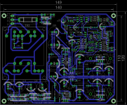
Please find in attachment suggestion for a new single channel PCB with PS and transformer included. It's just a little bit larger than the dual channel PCB and this one include pinout for Hammond 20VA transformer.
Please find in attachment suggestion for a new single channel PCB with PS and transformer included. It's just a little bit larger than the dual channel PCB and this one include pinout for Hammond 20VA transformer.
Attachments
Last edited:
Hi Prasimix,
actually I don't need the PS boards for two main reasons:
- the power supply of my pre-amps / phono stages is always made of a cap multiplier/linear regulator (which takes the line noise as low as possible) in series with a shunt regulator; I've tested many solutions and that's the one I like more in terms of sonic performance and satisfaction/perception; it has many drawbacks (complexity, used space, dissipated power,...) but it's the one I like more among simpler and/or more compact ones;
- the board dimensions of single PCB without PS (I intend to stack the two channels) is just right for the position where I intend to install it; it's a more complex preamp with a sort of lightspeed attenuator and PS in a separate case. The board with integrated PS would need a different case and I should completely change my project.
In my opinion, keeping separate the PS board from the single channel board let's you provide more flexibility in the final possible solutions of installation ... you can already get the dual channels board for the integrated solution ... but maybe it's only my self-interested opinion")
actually I don't need the PS boards for two main reasons:
- the power supply of my pre-amps / phono stages is always made of a cap multiplier/linear regulator (which takes the line noise as low as possible) in series with a shunt regulator; I've tested many solutions and that's the one I like more in terms of sonic performance and satisfaction/perception; it has many drawbacks (complexity, used space, dissipated power,...) but it's the one I like more among simpler and/or more compact ones;
- the board dimensions of single PCB without PS (I intend to stack the two channels) is just right for the position where I intend to install it; it's a more complex preamp with a sort of lightspeed attenuator and PS in a separate case. The board with integrated PS would need a different case and I should completely change my project.
In my opinion, keeping separate the PS board from the single channel board let's you provide more flexibility in the final possible solutions of installation ... you can already get the dual channels board for the integrated solution ... but maybe it's only my self-interested opinion
Thanks for your opinion.Hello,
I would like separate PSU/AMP pcb`s..that way i can change PSU if i like.
Gisle
When is closing time? Any update`s?
Thank`s
Gisle
It's still unknown. I need at least 20 pcs of any PCB to be in the same price range as was first time.
Hi Prasimix,
Thanks for all the hard work.
I have a few simple questions/concerns before I go ahead;
1. Is the Power Supply PCB an cap. multiplier or a simple regulator ?
2. Is there any component already soldered to the pre-amp PCB ? I'm mostly concerned about the BF862...soldering and matching them for a stereo set. Some GB includes that extra, paying more to get this is no problem.
3. I would go for the 2SK246/2SJ103 with the mandatory buffer. Are you planning to supply some sort of documentation that outlines the differences (if any) depending on your choices of JFET.
Depending on your answers I'd go for 2 x single channel + 1 power supply.
Thanks for your time,
Eric
Hi Prasimix,
Thanks for all the hard work.
I have a few simple questions/concerns before I go ahead;
1. Is the Power Supply PCB an cap. multiplier or a simple regulator ?
2. Is there any component already soldered to the pre-amp PCB ? I'm mostly concerned about the BF862...soldering and matching them for a stereo set. Some GB includes that extra, paying more to get this is no problem.
3. I would go for the 2SK246/2SJ103 with the mandatory buffer. Are you planning to supply some sort of documentation that outlines the differences (if any) depending on your choices of JFET.
Depending on your answers I'd go for 2 x single channel + 1 power supply.
Thanks for your time,
Eric
Hi Eric,
please note that I'm not the author of this design, but Juma and possibly cannot answer as good as him. PS is a cap. multiplier (in first version one resistor was missing but it is added in new layout).
BF862 is not soldered but it should not be a big deal to make it. I still have few of them and I can do that for you if you wish. As far as I know their matching is not necessary and P2 pot is used to set zero DC offset on each channel.
I do not have any plan to make such documentation but you can follow main thread and possibly learn more about difference.
Folks:
I've run into a problem and feel like an idiot, and am wondering how others building the LSK have dealt with it. I purchased Block FL18/18 encapsulated transformers for my project, not recognizing that the 18 VAC secondaries would never be able to generate the +/-33 VDC required by the LSK preamp. Stoopid.
I'm now looking at swapping out the transformers and am considering Block's FL18/24 (18 watts, 24 VAC secondaries). The next higher voltage available is 30 VAC, which I suspect will be too high.
Has anyone come up with a better solution? I'm using Prasimix's boards.
Regards,
Scott
Folks:
I've run into a problem and feel like an idiot, and am wondering how others building the LSK have dealt with it. I purchased Block FL18/18 encapsulated transformers for my project, not recognizing that the 18 VAC secondaries would never be able to generate the +/-33 VDC required by the LSK preamp. Stoopid.
I'm now looking at swapping out the transformers and am considering Block's FL18/24 (18 watts, 24 VAC secondaries). The next higher voltage available is 30 VAC, which I suspect will be too high.
Has anyone come up with a better solution? I'm using Prasimix's boards.
Regards,
Scott
Hm, that's strange since due to voltage doubler I had initially problem to be within a range of +/-37V that 7924 and 7824 regulators accept on input. The problem was fixed with adding an extra resistor as described in #217 in this thread. So no reason to feel like an idiot
Just check once again everything it should works fine as Juma promised and I can confirm.Folks:
Sorry for being so slow -- voltage doublers are new to me and I'm struggling to understand how they work and how adjust them. I am getting +/-23 to 24 VDC for the buffer stage on both single power supply boards, but roughly +/- 55 VDC for the input stage on both boards. These readings are with no load. The transformer is the Block FL 18/18 (18 VAC secondaries).
I don't understand why the input stage readings are so far off, when the buffer stage readings are on target. Is AndrewT's suggestion in post #211 (and prasimix's example in post #217) above the correct way to lower the input stage voltages down to the +/-33 VDC range?
Many thanks,
Scott
Voltage doublers (and triplers, etc) are difficult for me too.
I have to look at the sch/diag to work out where the parts go, it's not in my head.
But a voltage doubler does not perform as well as a bridge rectifier. Using the same component values you will find that the voltage drop as current flows is very much higher.
eg.
an 18Vac transformer feeding a bridge followed by 2200uF (for 1Adc output) will drop from an open circuit ~26Vdc to ~23Vdc
A doubler with the same 2200uF and supplying 1A will drop from an open circuit ~52Vdc to 30Vdc to 40Vdc accompanied by at least double the ripple voltage. Even reducing the output current to 500mAdc will not get you back to 46Vdc (double the ~23Vdc).
Due to the very high ripple voltage on the output of the doubler, you must look at the minimum voltage at the bottom of the ripple @ the output current you plan to use.
You need an oscilloscope to do this.
If the regulator or multiplier drops out due to the extreme ripple, then you will get a drop out (short period, ~1ms to 3ms, drop in voltage) that repeats every cycle of the mains. This will seriously affect the performance of the front end of the amplifier (or whatever audio circuit is being supplied).
Folks:
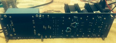
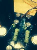
More confusion at my end. I modified one of my LSK power supply pcbs as recommended by AndrewT and prasimix but got unexpected results. The modifications involved repositioning R51 and R56 and adding 91K one watt resistors across C22 and C29 (see the photos). Following the modification, the input stage readings remain at about +/-54VDC while the buffer stage readings dropped from +/-24VDC to 0VDC. I'm clearly headed in the wrong direction.
Can you help me pinpoint my mistake?
Regards,
Scott
Attachments
prasimix:
R51 and R56 (both 470R 2W) were returned to their original positions and the buffer stage is back to +/-23 to 24VDC. Thank you!
Andrew:
I'm modifying to match posts 211 (yours) and 217 (prasimix). The reason for using 1 watt resistors is simple: I didn't have any 91k resistors on hand. A domestic source was selling inexpensive 1 watt versions. Low price, quick delivery -- who would complain?
All:
The input stage is still in the +/-54VDC range. Yes, the 91k resistors are in place across C22 and C29. How do you recommend getting the voltage down to +/-33 VDC?
Regards,
Scott
R51 and R56 (both 470R 2W) were returned to their original positions and the buffer stage is back to +/-23 to 24VDC. Thank you!
Are you referring back to the group of posts 208 to 219?
Are you modifying to match sch in post241?
Why 91k 1W?
P = V²/R
for 40V p=18mW
for 50V p=27mW
for 60V p=40mW
Andrew:
I'm modifying to match posts 211 (yours) and 217 (prasimix). The reason for using 1 watt resistors is simple: I didn't have any 91k resistors on hand. A domestic source was selling inexpensive 1 watt versions. Low price, quick delivery -- who would complain?
All:
The input stage is still in the +/-54VDC range. Yes, the 91k resistors are in place across C22 and C29. How do you recommend getting the voltage down to +/-33 VDC?
Regards,
Scott
prasimix:
All of the parts were sourced from Mouser and Allied Electronics, so I trust they're legitimate.
Q19 is an IRF610. Voltage readings to ground:
G = 54.5 vDC
D = 60.7 vDC
S = 51.7 vDC
Q20 is an IRF 9620. Voltage readings to ground:
G = 54.4 vDC
D = 60.6 vDC
S = 51.7 vDC
I verified the values and orientation of the following parts:
R27 & R55 (100R 2W)
C20 & C27 (1000uF 50v)
D9 & D14 (1N4007)
R53 & R58 (10k 0.6W)
R54 & R59 (330R 0.6W)
C22 & C29 (220uF 50v)
What readings would help diagnose this problem?
Regards,
Scott
- Status
- This old topic is closed. If you want to reopen this topic, contact a moderator using the "Report Post" button.
- Home
- Group Buys
- Juma's LSK Preamp - through hole version