
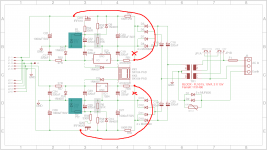
I tried to add actually two resistor to came down to +/-24 and +/-33V with 2x15V 10VA transformer. Check schematic below.
Dissipation of 2K resistor is around 500mW, and 240R around 1.3W.
Is this a special case or is this in general?
I have a 2x18v AC trafo but have not yet tried it on the board (waiting on the jfets)
just so that I don´t burn sommething...
Can a stereo pair of boards be run off a single power supply?
Yes, of course. That is a case with dual channel PCB what is my first choice and works just fine.
Is this a special case or is this in general?
I have a 2x18v AC trafo but have not yet tried it on the board (waiting on the jfets)
just so that I don´t burn sommething...
It's in general with small transformer with considerable no load voltage factor like models suggested in BOM. Before you connect single channel preamp PCB just check if you have around +/-33V for input stage and +/-24V for buffer section. Especially pay attention on -24V because if input voltage is over -40V it's possible that it cannot provide correct output voltage. I didn't notice that with positive regulator (7824) which is from another manufacturer.
would it help dissipation further adding a LED to the drain ? (especially the 240R at trafo side)
noticed now the drain 240R is mounted directly on trafo secondary ?
shouldn't it be after bridge and first smoothing caps ?
I posted this this morning, but it got lost somewhere.
Add a high value resistor in parallel to C22 and another parallel to C29, to get the cap multipliers working properly.
Try connecting the OUTPUT of the transistors Q19 & Q20 to the input resistors, R51 & R56, to feed a lower and smoothed voltage into the regulators.
Add a high value resistor in parallel to C22 and another parallel to C29, to get the cap multipliers working properly.
Try connecting the OUTPUT of the transistors Q19 & Q20 to the input resistors, R51 & R56, to feed a lower and smoothed voltage into the regulators.
I posted this this morning, but it got lost somewhere.
Add a high value resistor in parallel to C22 and another parallel to C29, to get the cap multipliers working properly.
How much, in tens or hundreds of kohms, in mohms?
Try connecting the OUTPUT of the transistors Q19 & Q20 to the input resistors, R51 & R56, to feed a lower and smoothed voltage into the regulators.
I don't understand this. You mean some resistor, or resistor voltage divider? Could that also help that 24V regulators have below 40V on inputs?
noticed now the drain 240R is mounted directly on trafo secondary ?
shouldn't it be after bridge and first smoothing caps ?
I thought that in such way it will be less demanding for input capacitors used for voltage multiplication.
For R53 = 10k try the extra R=90k (actually 91k)How much, in tens or hundreds of kohms, in mohms?
The voltage on the capacitor will be ~90% (91k/[91k+10k]) of the average voltage at the input.
The output voltage will be capacitor voltage minus Vgs of the pass device.
With the larger Vds, the Vgs will vary less with changes in current demand.
This is the big difference between a proper capacitor multiplier and the version in post200.
You can change R53 to any value, to vary the percentage of the input voltage that appears on the capacitor. anywhere from 50% to 99% would be experimental values. Try to stay between 80% and 95% for usable multiplier.
If the pass device is a BJT, the base current has to pass through R53. It must be a much lower value. Try 1k : 10k for a 91%, if the power dissipation is OK.
Last edited:
...................
Try connecting the OUTPUT of the transistors Q19 & Q20 to the input resistors, R51 & R56, to feed a lower and smoothed voltage into the regulators.
Use the output of the multiplier to feed the regulator..............I don't understand this. ...........
For R53 = 10k try the extra R=90k (actually 91k)
The voltage on the capacitor will be ~90% (91k/[91k+10k]) of the average voltage at the input.
The output voltage will be capacitor voltage minus Vgs of the pass device.
With the larger Vds, the Vgs will vary less with changes in current demand.
This is the big difference between a proper capacitor multiplier and the version in post200.
You can change R53 to any value, to vary the percentage of the input voltage that appears on the capacitor. anywhere from 50% to 99% would be experimental values. Try to stay between 80% and 95% for usable multiplier.
If the pass device is a BJT, the base current has to pass through R53. It must be a much lower value. Try 1k : 10k for a 91%, if the power dissipation is OK.
Tested with approx 90K and it seems like right value with my 2x15V 10VA transformer and two channel connected on single PS board. For one channel that value probably should be much less (40-50K).
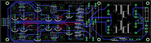
This is also an elegant solution since you just need to solder that resistor on bottom side of the PCB directly to the capacitor pins (C22 and C29). Thanks for this suggestion.
Use the output of the multiplier to feed the regulator.
Oh, now I see. I didn't try that since that will require more surgery on the PCB
")
Surgery ?Oh, now I see. I didn't try that since that will require more surgery on the PCB
Just link the resistor across the two pads.
omitting the resistor in the input to ground series ladder destroys the capacitance multiplier.Tested with approx 90K and it seems like right value with my 2x15V 10VA transformer and two channel connected on single PS board. For one channel that value probably should be much less (40-50K).
This is also an elegant solution since you just need to solder that resistor on bottom side of the PCB directly to the capacitor pins (C22 and C29). Thanks for this suggestion.
Use the tapping point between the two series resistors to define the base/gate voltage of the pass device.
You can also add yet another resistor+diode across that capacitor.
This converts the simple multiplier into a (soft) regulator, if the input voltage goes too high. Experiment with resistor and Zener values to see what can be achieved. I did a spreadsheet way back last century to make the calculations quickly.
omitting the resistor in the input to ground series ladder destroys the capacitance multiplier.
Use the tapping point between the two series resistors to define the base/gate voltage of the pass device.
You can also add yet another resistor+diode across that capacitor.
This converts the simple multiplier into a (soft) regulator, if the input voltage goes too high. Experiment with resistor and Zener values to see what can be achieved. I did a spreadsheet way back last century to make the calculations quickly.
I'm enclosing proposed corrections as you suggested (and if I understood you correctly). I didn't add extra R+Zener in parallel with C22, C29 on the PCB drawing (components shaded green on schematic).
Attachments
How did you adjust the pots?
Just to finally address this question: Use P1/P4 to find 0VDC on pot's viper pin (or R6/R33 leg) and P2/P5 to set 0VDC at buffer output.
Don't forget to ground input and I found oscilloscope more appropriate for that job then DVM.
prasimix & Co.:
I've been distracted the past few months and am only now about to start working on this project. Prasimix's latest posts have me worried -- I bought a pair of FL18/18 transformers from Allied Electronics (Block - FL 18/18 - Uncategorized - Allied Electronics) and am wondering if I should have gotten the 15VAC version instead.
I can check to see how these transformers are performing before soldering them onto the power supply pcb, but can anyone clue me in on what the unloaded output of these things ought to be? It'll presumably be something North of 18V, but what should the maximum acceptable output on the secondaries be for this project?
Thanks for helping this dope out.
Regards,
Scott
- Status
- This old topic is closed. If you want to reopen this topic, contact a moderator using the "Report Post" button.
- Home
- Group Buys
- Juma's LSK Preamp - through hole version