Dual Secondaries are more common than centre tapped.
Probably because any dual secondary can be converted to centre tapped at no cost, but centre tapped cannot be converted back to dual secondaries.
Some prefer the semi-isolated nature of the dual bridge's Power Ground from the Transformer windings. There is also a small advantage if the current draw of the -ve and +ve halves are not identical all the time.
Here is what I could come up with for the reg PSU, like Fred said, one could use D4XH11 or try with TIP4XX or TIP3XX.
For LM and TIP, One could use either a heatsink or mount on the bottom on case or use an aluminium plate as a heatsink. Mounting hole options as per heatsink choice.
reg
Prasi
also possible to convert into diy-etching job, with hardly any change!
") ... like this
... like thisAttachments
yes thats a good and cheap option or you could also do like Fred suggested (universal power supply).PSU's also lend themselves to P2P with veroboard (or in some cases dead bug style). I might have a go at this with veroboard. Will squeeze each half onto 4x6cm board.
A small personal favor to ask, may I have a +ve only board's .brd when this is final? The reason is that I have a lot of LM317's and not enough LM337
Thanks!!
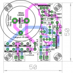
here is the LM317 only pcb, if you are done with testing your hack job of the universal psu
.What is the cap size you are using? I have it at 30mm dia and is quite big for a 50mmx50mm job. pcb might need a small support on the bottom where the forth mtg hole is located.
the LM and D44/TIP still have to be mounted on case for sinking the heat. see if you find it useful.
reg
prasi
Attachments
Love it!!here is the LM317 only pcb, if you are done with testing your hack job of the universal psu
What is the cap size you are using? I have it at 30mm dia and is quite big for a 50mmx50mm job. pcb might need a small support on the bottom where the forth mtg hole is located.
the LM and D44/TIP still have to be mounted on case for sinking the heat. see if you find it useful.
reg
prasi
The cap that I am using for the universal board has 25mm diameter. There are plenty of selections from the 25mm/25.4mm and 10mm lead space.
X, yes, you can stack 2 of these (tie the gnd to the +ve of the other) to create a bipolar supply. That's how I plan to use these boards.
Thanks!!!
Hi Eric,
Oliver (Stixx) has many different cans and good ears. He has no noise issue with
the Nazar reg using the LM regs, but yes, LT is better, and you can use any LT 3-pin reg as long as it is pin compatible to the LM's such as LT1086.
Prasi, email me the LM317 .brd at your convenient, and I will send it over to Dirty to get some protos to test
Thanks!!
Hi Eric,
Oliver (Stixx) has many different cans and good ears. He has no noise issue with
the Nazar reg using the LM regs, but yes, LT is better, and you can use any LT 3-pin reg as long as it is pin compatible to the LM's such as LT1086.
Prasi, email me the LM317 .brd at your convenient, and I will send it over to Dirty to get some protos to test
Thanks!!
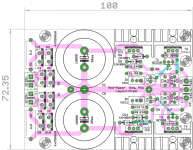
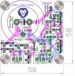
Fred, how about this one, even more cuter
and convenient to mount on case wall or main heatsink as both the LM and TIP along the same edge of pcb!!. 25mm cap will fit easily, no probs... with this version, even 35mm cap can be fitted.. just needed to spend some time on the layout
 ...
...reg
Prasi
Attachments
Last edited:
This version neater and can be mounted to the main heat sink.Fred, how about this one, even more cuter
just needed to spend some time on the layout
reg
Prasi
One observation from my hack up version, the 3.3R can get a little hot for the the BC560 to sit right next to it. I tried up to load to 500mA to simulate 250mA per channel, it was
 I will move the BC560 away from the heat source if possible. However, it is not a deal breaker, we can always mount the BC below the board or raise the 3.3R up more in the air
 My gut feeling is that the 1st version may work better in most of the HA chassis because the main heat sink height is not tall enough for 2 to stack together.
For either version, I will move the TO-220 devices out to the edge as much as possible for ease of mounting a heat sink on the side.
Thanks!!
One observation from my hack up version, the 3.3R can get a little hot for the the BC560 to sit right next to it. I tried up to load to 500mA to simulate 250mA per channel, it was
were you using 1W or 2W resistor? with 500mA, Its about 0.825W. The package I have now is for 2W. Also with resistor being vertical, it will help in dissipating heat better (gut feeling). anyway, I have moved it (and the C2 cap) slightly away from the resistor and should now be ok.
reg
Prasi
Attachments
Hi Prasi,
I used 3W for both the 3.3R and the 2.7R.
It was a little exaggerate But moving the BC a little away will certainly help stability as the little TO-92 doesn't like hot.
X, ignore the silkscreen and consider that as AC input and DC output.
In my test, I had 12.6VAC in, and 11.5VDC output. If you want 15VDC out, then you will use a 15VAC transformer.
Here is a cut&paste from Nazar's site:
where
R4 is Prasi's VR3.
R2 is Prasi's R4.
VT1 and VT4 are the BC560C and BC550C.
You can adjust this board to fit your use with the appropriate transformer for other application that fits. The only restriction is the input voltage of the 3-pin reg. So, 25VAC is likely the max you want to use.
I just sent the order to DirtyPCB, let see I will get it back by Thanksgiving to play with
I used 3W for both the 3.3R and the 2.7R.
It was a little exaggerate
But moving the BC a little away will certainly help stability as the little TO-92 doesn't like hot. X, ignore the silkscreen and consider that as AC input and DC output.
In my test, I had 12.6VAC in, and 11.5VDC output. If you want 15VDC out, then you will use a 15VAC transformer.
Here is a cut&paste from Nazar's site:
The calculation of the scheme under the desired settings is not difficult, according to the desired output voltage and maximum output current calculated values of resistors R4, R6 and R2, R10, respectively, for the formulas below
R4 = 240 * (Uout-Ube) / 1.25
R2 = (1.25-Ube) / ((0.3 / Uout) + Ir),
where the output voltage Uout-In, Ube-base-emitter voltage of transistors VT1, VT4 In, Ir - load current A.
where
R4 is Prasi's VR3.
R2 is Prasi's R4.
VT1 and VT4 are the BC560C and BC550C.
You can adjust this board to fit your use with the appropriate transformer for other application that fits. The only restriction is the input voltage of the 3-pin reg. So, 25VAC is likely the max you want to use.
I just sent the order to DirtyPCB, let see I will get it back by Thanksgiving to play with
I have a general question about protecting headphones from excessive output. These amps have 15v rails and if something should let loose, or we inadvertently plug in source without setting volume knob to zero could send a spike and kill a nice headphone driver with over excursion. A SS MOSFET protection circuit might work but adds complications. Could not say a 4.8v Zener back to back clamp on the output work or would that hurt SQ?
were you using 1W or 2W resistor? with 500mA, Its about 0.825W. The package I have now is for 2W. Also with resistor being vertical, it will help in dissipating heat better (gut feeling). anyway, I have moved it (and the C2 cap) slightly away from the resistor and should now be ok.
reg
Prasi
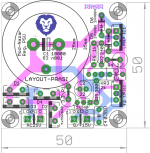
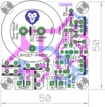
here is a 337 version on the same lines. it seems, one could use the same 317 board and take care of diode orientation, capacitor orientation and LM337 pin config, then same board could be used
.Attachments
I have a general question about protecting headphones from excessive output. These amps have 15v rails and if something should let loose, or we inadvertently plug in source without setting volume knob to zero could send a spike and kill a nice headphone driver with over excursion. A SS MOSFET protection circuit might work but adds complications. Could not say a 4.8v Zener back to back clamp on the output work or would that hurt SQ?
Also same question, how about a PPTC, or TBU (Bourns Transient Blocking Unit) ?
stax used a MOV or something in their electret ear speakers, (phones) srx-40/80
- Home
- Amplifiers
- Pass Labs
- Juma's Head Amp