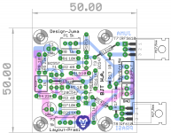
This is a layout for the Juma's Headphone Amp posted here http://www.diyaudio.com/forums/pass-labs/271926-f5-headamp.html#post4269989 . Some members seem interested in this") .
.
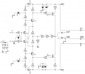
the schematic is attached here again for convenience.
will post gerbers later..
edit
schema, left channel here http://www.diyaudio.com/forums/pass-labs/298369-jumas-head-amp-52.html#post4978271
layout stereo pcb here http://www.diyaudio.com/forums/pass-labs/298369-jumas-head-amp-51.html#post4978066
bom for stereo pcb here http://www.diyaudio.com/forums/pass-labs/298369-jumas-head-amp-41.html#post4920913
PSU,
schema and layout for dual rail psu here http://www.diyaudio.com/forums/pass-labs/298369-jumas-head-amp-48.html#post4937986
bom for dual rail psu here http://www.diyaudio.com/forums/pass-labs/298369-jumas-head-amp-41.html#post4920948
.the schematic is attached here again for convenience.
will post gerbers later..
edit
schema, left channel here http://www.diyaudio.com/forums/pass-labs/298369-jumas-head-amp-52.html#post4978271
layout stereo pcb here http://www.diyaudio.com/forums/pass-labs/298369-jumas-head-amp-51.html#post4978066
bom for stereo pcb here http://www.diyaudio.com/forums/pass-labs/298369-jumas-head-amp-41.html#post4920913
PSU,
schema and layout for dual rail psu here http://www.diyaudio.com/forums/pass-labs/298369-jumas-head-amp-48.html#post4937986
bom for dual rail psu here http://www.diyaudio.com/forums/pass-labs/298369-jumas-head-amp-41.html#post4920948
Attachments
Last edited:

If I were building this I would add passive filtering to the input.
For my headphones I would need a lot less gain. As shown it is about +14.9dB
An input filter will reduce the overall gain very slightly.
I would want to try reducing R16 form 1k to ~270r (maybe three 130r in series). Then it's easy to short out one, or two, to acheive a stepped gain. But I would also need to check that the increased feedback did not interfere with the stability margins.
If I were building this I would add passive filtering to the input.
For my headphones I would need a lot less gain. As shown it is about +14.9dB
An input filter will reduce the overall gain very slightly.
I would want to try reducing R16 form 1k to ~270r (maybe three 130r in series). Then it's easy to short out one, or two, to acheive a stepped gain. But I would also need to check that the increased feedback did not interfere with the stability margins.
You mean like the usual 330pF to ground (combined with say 1k or 2k2 in series to input pin) for RF suppression? I agree 12dB would be a better gain value for headphones. I am using the F5HA with no input RF filtering and seems to work fine, although I have not plugged into a big DAC which sometimes generates its own RF.
The F5 has high input capacitance. Many use this as an RF filter. But for me it rolls in too high up the frequency range. Some claim F5 FR extends to the MHz. That's about a decade higher than I would use.
Typically I use 160kHz to 240kHz. And 1Hz to 2Hz, i.e a decade wider than the audio band.
The cascode in some versions of the F5t reduces that input capacitance.
Digital outputs can contain lots of frequencies at surprising high levels not far above the audio band. These types of Sources deserve more severe filtering than a passive single pole @ 200kHz. 3 pole active @ 50kHz?
Last edited:

I was not asking you to change your design.
It was a suggestion that could be implemented fairly easily on your PCB as was, to help with using the heaphone amp with some environmental interference and sensitive headphones.
If one were to use 3off 130r and 220r as the fedback pair then the gains become
{390/220}+1 * 22k/22k22 = +8.77dB
{260/220}+1 * 22k/22k22 = +6.90dB
{130/220}+1 * 22k/22k22 = +3.96dB
And much leeway to choose other resistor values, even reverting to 3*330r for almost 1k
But do check stability margins at these lower gains.
Can someone do an LTspice to predict how it would/might behave?
Last edited:
That looks great Prasi. Thanks for using screw block terminals, bigger 1000uF cap, and SMT pad for 100nF bypasses.
I should be careful (you too x) with, whose name we use as the designer. Some people are too sensitive, even if you add one extra component, they deny all responsibility for the circuit (as if its a bomb, one wire/component here and there, no matter how benign, kaboom!)..
I have added many components here, however I would like OR I am sure Juma would not mind to be still called as the designer. Your blessings requested here Juma..
always best to take permission first..
I have added many components here, however I would like OR I am sure Juma would not mind to be still called as the designer. Your blessings requested here Juma..
always best to take permission first..
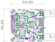
The latest version is essentially the same as the original with a few options for experiment so to speak. As a matter of fact, all the AndrewT suggestion can be implemented from the original PCB design in post #1, just doesn't look as neat.
IMHO, I will still call it Juma F5 BJT HA.
Slightly OT, I purchased a few PCB designed by other members from dirtypcb, but it requires to upload the .brd file. From the site:
Thanks!!
IMHO, I will still call it Juma F5 BJT HA.
Slightly OT, I purchased a few PCB designed by other members from dirtypcb, but it requires to upload the .brd file. From the site:
So, is it possible to provide the .brd file in addition to the gerbers?Submit Cadsoft Eagle .brd files directly and let us create the gerbers! 2 layers only. .brd files are processed with Eagle v6.x and we noticed a bug on a single order using v7.1.0 files. It's probably best to make your own gerbers if you used Eagle v7+.
Thanks!!
thats all i needed Juma, thanks a lot...Guys, it's a public domain - you can do with it whatever you want and call it however you want. I just published the circuit that I've built and liked, so why shouldn't you change it into something that you might like better? No IP, no royalties, just fun...
Cheers !
best regards,
Prasi
if you need this pcb, just PM me with your email, and you will get gerbers and.brd and .sch too....The latest version is essentially the same as the original with a few options for experiment so to speak. As a matter of fact, all the AndrewT suggestion can be implemented from the original PCB design in post #1, just doesn't look as neat.
IMHO, I will still call it Juma F5 BJT HA.
Slightly OT, I purchased a few PCB designed by other members from dirtypcb, but it requires to upload the .brd file. From the site:
So, is it possible to provide the .brd file in addition to the gerbers?
Thanks!!
if you are looking for conversion of your .brd file into proper gerbs, you can PM me , i would do that for you....
slightly OT, I always wanted it to be called Juma BJT HA , the background for my concern could be found at recent posts in 'post your solid state pics here' thread...
regards
Prasi
I should be careful (you too x) with, whose name we use as the designer. Some people are too sensitive, even if you add one extra component, they deny all responsibility for the circuit (as if its a bomb, one wire/component here and there, no matter how benign, kaboom!..
Yes, you have to be careful with adding those ground lift resistors and back to back diodes. They might go kaboom.
Ok done... Gerbers on request
Listen to Juma...think of EUVL...
it's public
Publish the gerbers....don't make a big deal of it.
...upon request....come on....anyway it is way different from the original....share ...recognize the gift EUVL gave you.
Last edited:
- Home
- Amplifiers
- Pass Labs
- Juma's Head Amp