Hi Mike, John,
I'll root around a bit. In the meantime I'll try to post some pics of the phono board itself.
This design would be from the very late 70's when Marantz produced it's best equipment (in my personal opinion). I think it may have been discontinued in 1980. It's notable that the phono board from the 3650 was also used in the top of the line SC-9 also.
I own both. Bad switch contacts on both pieces!
-Chris
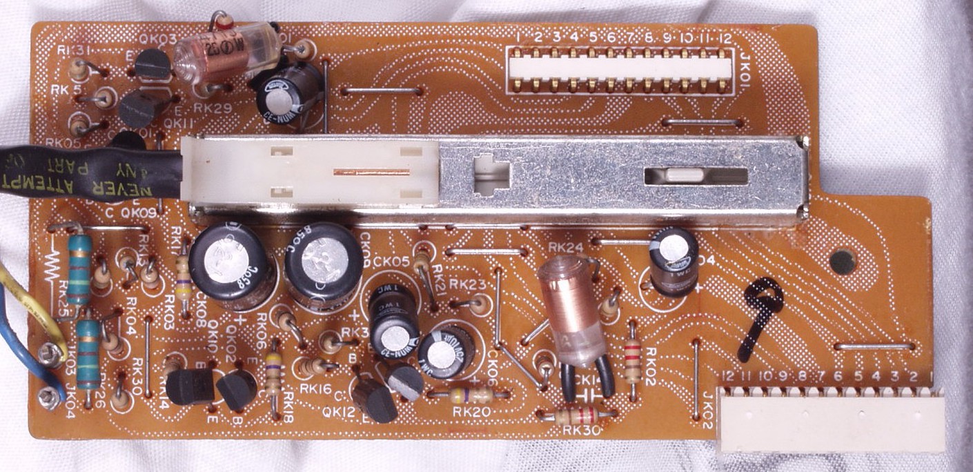
Phono Eq
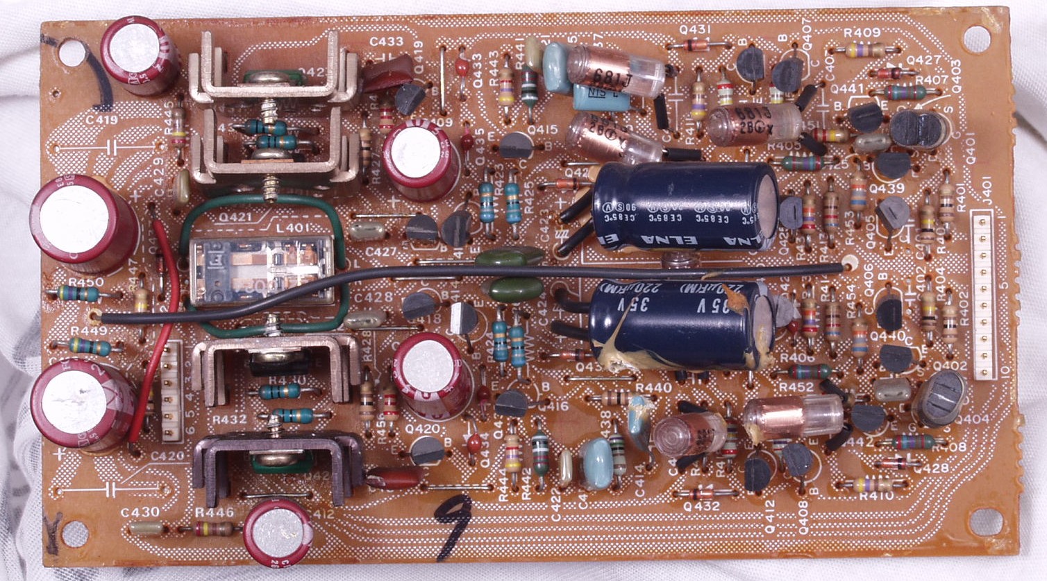
MC Amp
I am linking to these at http://amp8.com/tr-amp/marantz/pre_amp/sc-9.htm beware the page is over 20meg.
Regards
James
john curl said:Grey, with the stand-up resistor. Do you really think that they can REMOVE all residual inductance from a resistor? Maybe, they can just reduce it to the equivalent to a straight wire. That inductance WOULD cancel the the return lead length. What do you think?
Now you've gone and posed an interesting question. I can argue it six different ways from Sunday, but lacking hard data, it would only be speculation.
However...
I am on fairly good terms with one of the tech honchos at Caddock, in that he knows me in my "other" life (meaning he reads my stories). I'll pose the question to him and see what he says. Obviously, the reply would only be applicable to Caddock products, but I can't imagine that their design practices would be outlandishly different from Vishay, Roederstein, et. al.
The photos above illustrate graphically what I was trying to say in an earlier post. Note that a lot of the resistors are mounted vertically. Note also that a lot of them are leaning (as are the caps). Even given that they've oriented the resistors' leads such that they alternate, it's not too much of a stretch of the imagination to see that they could short if they lean together. The obvious response is: Then put sleeves on the leads. To which I say that they are still susceptible to mechanical damage such as stress on the end caps of the resistors, welds on leads to plates in capacitors, and...if we are to count magnetic and/or static coupling between parts as a possible contributor to the sound of a piece of equipment, then that's going to vary widely depending on whether they lean towards a resistor on one side or a JFET on the other. You catch my drift. If there is any basis for assuming that a component can couple to an adjacent part, let's knock out as many variables as possible--for product consistency, if for no other reason.
As it happens, I'm working on a discrete phono stage, also. Balanced, passive EQ, no feedback, the works. It's on the back burner at the moment, as I'm putting what little time I can spare into the amp circuit. (Parts are in--need to cook a PCB.)
Grey
Yes, that's an interesting question. With a true induction free resistor cell, my guess is we could get as low as a similar length of a shorted twisted pair wire (two wires with ~10nH/cm, coupled with K=0.7..0.8, would give ~4nH for a 1cm height), if we manage to get the loop area as small as possibly, with a snug fit of the return wire to the exact shape of the R. That would provoke heavy stress on the leads and end caps, or we could alternately use a soldered/crimped return wire, both I'd consider suboptimal. And we would increase capacitiance this way, which might not be a problem dedending on application.
I'm curious about what the Caddock tech will have to say to this...
- Klaus
I'm curious about what the Caddock tech will have to say to this...
- Klaus
Hi James,
I was about to ask if you had one.
I've seen that site you linked to. This guy likes to replace parts and add solder (too much!) without cleaning up after himself. I've seen work he's done much worse than this.
So, if your soldering looks like the after shots people, time to learn how to work. Never add too much solder. Never fail to clean the flux off. If you look closely, you will see that not all joints are done properly even with all that excess solder.
-Chris
I have e-mailed the fella regarding induction in resistors. In the meantime, my gut feeling is that it won't cancel because the cross section of the body would tend to distribute whatever residual inductance is left in the resistor; the majority of the magnetic field would be far enough away from the long lead that it couldn't be canceled.
But hopefully I'll get a reply in the next day or two saying one way or another.
Grey
But hopefully I'll get a reply in the next day or two saying one way or another.
Grey
Now there's a blast from the past... Anyone with there hands in the equipment at the time will feel right at home.
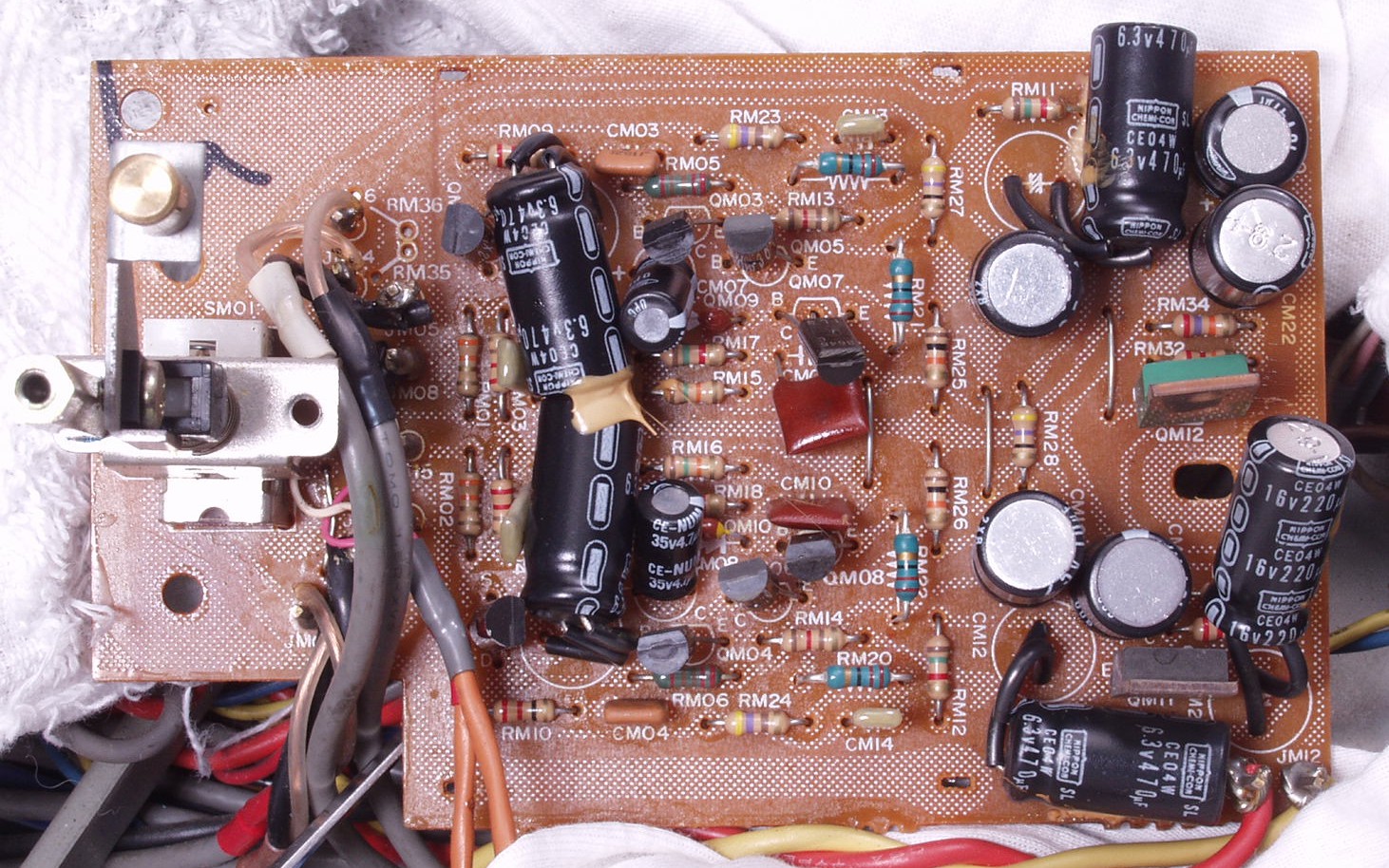
Ya gotta love the phenolic pcb, polystyrene caps with what looks like copper foil. I remember the dark blue and the maroon electrolytics as being very good sounding as electros go. Wire wrap terminations to the boards, carbon film resistors with a few metal films where needed.
I'd love to hear it in my system, my guess is it wouldn't do to bad. Then I'd take the same circuit, give it a decent layout and modern power supply and listen again.
I'm curious as to what the preamp sold for when new. Most likely a very small fraction of stereophile middle of the road stuff these days.
I remember the style of switches seen on the board as being terrible. I got real good at diamantling them and rebuilding them. White plastic pencil erasers so as not to damage the platings and GC high freq contact grease...
Mike.
Hi Grey,
Having a resistor act as an antenna is a valid point possibly. But then again, your capacitors stand up mostly also. They have a larger surface area on top of that. I think we just got side tracked.
-Chris
If the resistor is mounted horizontally, there would be no to little cancellation as well (thinking of a parallel trace). I don't see this as a discussion since you can not change much.In the meantime, my gut feeling is that it won't cancel because the cross section of the body would tend to distribute whatever residual inductance is left in the resistor;
Having a resistor act as an antenna is a valid point possibly. But then again, your capacitors stand up mostly also. They have a larger surface area on top of that. I think we just got side tracked.
-Chris
Hi Mike,
Those preamps passed virtually unknown by most. I can't remember the price, but I'm super glad I have them. I honestly have not heard better - yet. I am trying to replace them without too much luck so far.
I cracked one switch in half on my SC-9. First attempt at repair failed. So I'll dive in again when I have the energy. I think you would be surprised listening to them. Other people over at my house have tried many preamps against these and left wondering why they were not better known. Mind you, there was a backlash against Superscope at the time.
-Chris
anatech said:Hi Grey,
If the resistor is mounted horizontally, there would be no to little cancellation as well (thinking of a parallel trace). I don't see this as a discussion since you can not change much.
Having a resistor act as an antenna is a valid point possibly. But then again, your capacitors stand up mostly also. They have a larger surface area on top of that. I think we just got side tracked.
-Chris
My operating hypothesis at the moment is that parts selection, in the sense of manufacturer and resistor type, would swamp anything the builder could achieve by diddling parts placement. It would, at best, be one of those fine-tuning things that you do after you've perfected everything else you can think of. As I said above, I favor horizontal mounting anyway.
Regarding caps, you're going to get at least some shielding, assuming that the grounded plate is on the outside. That's something that resistors don't have.
...Sooooo...okay, what if you were to shield resistors?
Given that RF is a known, real problem (i.e. even specs-uber-alles folks can get behind RF troubles, yes?), what if you were to use a grounded copper foil shield over critical resistors? It would be trivial to cut a square, say, a half-inch per side, form it over a round-shaft screwdriver, flatten the ends back out with needle nosed pliers (thus creating something like an omega [naturally, since we're talking resistors] in cross section), then solder the flat tabs to grounded pads on either side of the resistor. For that matter, it could serve as a smallish heatsink for the resistor if needed.
Yes, John, I know that a milled chassis out of a hundred pound slab of aluminum would do the trick, but this would be much cheaper.
Grey
P.S.: Come to think of it, I've got some sheet copper, somewhere in the Dungeon. You used to be able to get it in art supply stores. I don't know if that's still the case.
Hi Grey,
Granted. I can accept your position.
Shielding each large coupling capacitor (shield at a distance) is probably worthwhile.
I think it comes down to trade offs as each cure may bring with it, a problem. No one method would work throughout a design.
-Chris
Granted. I can accept your position.
I would think that a metallic "U" around each part would be overkill even. Boxing low level stages would take care of most of your troubles. One thing you really would have to watch is any added capacitance due to shielding each part. A problem would have been created....Sooooo...okay, what if you were to shield resistors?
Shielding each large coupling capacitor (shield at a distance) is probably worthwhile.
This does not occur with coupling caps.Regarding caps, you're going to get at least some shielding, assuming that the grounded plate is on the outside.
I think it comes down to trade offs as each cure may bring with it, a problem. No one method would work throughout a design.
I think you still can. Good thought!You used to be able to get it in art supply stores.
-Chris
") Sorry to interfere this threads but it seems the TDK step pot on the
Sorry to interfere this threads but it seems the TDK step pot on the
GRollins said:
My operating hypothesis at the moment is that parts selection, in the sense of manufacturer and resistor type, would swamp anything the builder could achieve by diddling parts placement.
Hi Grey,
By parts placement I'm assuming that you're referring to the difference between horzontal or vertical mountings, not the physical location on the board or the sequence of the electrical connections in a circuit. This I can be quite important. This concept was substantiated in a app note recently discussing the correct connection of an offset adjustment to an opamp. The gist was that a stability issue arose when you connected the wiper of the adjustment to the supply rail as opposed to connecting it directly to the amps supply input pin.
Experimentation over the years has shown that the sequencing of connections can have an effect on the performance. (where the output signal is drawn from a stage, at the gain device or the load resistor, as an example) The logic guiding this approach is still evolving, but it does appear to make a difference.
...Sooooo...okay, what if you were to shield resistors?
Given that RF is a known, real problem (i.e. even specs-uber-alles folks can get behind RF troubles, yes?), what if you were to use a grounded copper foil shield over critical resistors? Yes, John, I know that a milled chassis out of a hundred pound slab of aluminum would do the trick, but this would be much cheaper.
Grey
P.S.: Come to think of it, I've got some sheet copper, somewhere in the Dungeon. You used to be able to get it in art supply stores. I don't know if that's still the case. [/B]
Minimizing the places that RF can enter a circuit (layout) and controlling the environment the circuit functions in (casework) are better than local shielding. The reasoning is that any local shielding has a capacitive or magnetic effect (current flows) on the signal. Any interaction involves the disappation of part of the signal, or a charge/discharge function that has a reactive affect on the signal passing through. Ground planes exhibit a similar effects. The signal path is either being affected by the plane to ground connection or part of the signal is being coupled elsewhere in the circuit through the plane. It's very hard to control ground.
Hobby stores in the US sell sheet copper, thin sheets are also available from Small Parts Inc. Great for building small enclosures by soldering the joints.
Regards, Mike.
anatech said:Hi Mike,
Those preamps passed virtually unknown by most. I can't remember the price, but I'm super glad I have them. I honestly have not heard better - yet. I am trying to replace them without too much luck so far.
I cracked one switch in half on my SC-9. First attempt at repair failed. So I'll dive in again when I have the energy. I think you would be surprised listening to them. Other people over at my house have tried many preamps against these and left wondering why they were not better known. Mind you, there was a backlash against Superscope at the time.
-Chris
Hi Chris,
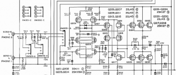
I've tried to come up with a schematic for the SC-9 with no luck. I'm curious as to whether there was something special going on circuit wise or if the execution says something about why it was special. I went to TheVintageknob.org and they had pictures of a couple others in the series. Maybe when you get a chance you or James can post an overall picture of the insides. I tend to be drawn to the oddball stuff. Do you have a schematic?
Thanks, Mike.
john curl said:I am happy to see new phono stage designs. I am making two, myself, at this time. One IC, one all FET discrete.
I know from experience that discrete is better, but IC's might be OK with the NEWER topologies, such as used by National Semi.
The single stage technique, first done with tubes for decades, is not really adequate. However, a two stage design can be really successful.
Hi John,
Are you designing your IC based circuit around the National chips or do you have another, possibly a FET, input chip in mind? Or will the circuit be universal enough to allow you to choose any?
Regards, Mike.
Hi Mike,
These preamps (SC-9 and 3650) are combinations of diamond transistor arrangements for buffers and differential J Fet type signal amplifiers. I am very impressed with this preamplifer design.
So far, nothing I have heard comes close. It's really not there in the signal path. It causes the least damage to the signal of any preamp I have heard. The phono stage is very quiet and the highs have no harshness. What more can I say?
-Chris
Edit: The SC-9 is basically a 3650. The volume control is different and the SC-9 adds a headphone amp. The rest is the same.
- Status
- Not open for further replies.
- Home
- Amplifiers
- Solid State
- John Curl's Blowtorch preamplifier