.john curl said:Actually, j-fets will run reasonably OK at OV bias, and you can forward bias them slightly without any real problem. This is because today's low noise fets have so much Gm that even .1V forward bias can a lot of current, in proportion to what is necessary. Another factor is that the junction in j-fets seems to be at a fairly hard junction to get current flowing, compared to some devices. This means that .1-.3V forward bias, in most situations will not change things much. This is NOT true with very high Z microphone inputs, etc. However, most sources are below 100K ohm.
Hi John,
All of the fet input stages I have used have mimiced the commonly used approaches. I'm stepping into new territory with a FET input MC circuit. I'm trying to keep it basic and learn, but still worry what I'll be subjecting my cartridge to. Up until today I assumed that a Fet with a Vp 0f .5 v would respond from 0 to Vp. I guess now that that is not so. I never gave it much thought
The bias you are talking about is accomplished by inserting a source resistor and the Idss raises the source above ground effectively biasing the gate?
Does matching the Idss of a symetrical K and J pair in and input stage actually produce equal bias at the N and P sources? Does one need to control this bias accurately between the upper and lower half?
In my line amp I have the +/- sources in series and floating with no ground reference. I'm assuming this won't work in a MC amp. Am I wrong? I'm assuming that I will need to bias each half to the opposite supply. Would ground work, something like an offset pot with the wiper grounded? Am I worrying about nothing?
Hopefully the questions are not to basic. It's new ground for me.
Mike.
") I pretty much butchered what I was trying to ask.
I pretty much butchered what I was trying to ask. MikeBettinger said:
With a MC cartridge as an input (outputting a bipolar signal) I have wondered about the nonlinearity a normal fet might exhibit as the cartridges output swings both negative and positive.
..............................................
It's new ground for me.
Mike.
Outputting a bipolar signal?!
Is the new ground called AC?
MikeBettinger said:In my usual distracted manner I missed the link to the SC-9 site. The images answer most of my questions. Thanks. Schematic for these two seem to be unobtainable at the moment.
Regards, Mike.
Here for some bucks:
http://www.manuals-in-pdf.com/advanced_search_result.php?keywords=marantz+sc9+manual&forward=plist
Or here for 3650:
http://www.analogalley.com/m_marant.htm
With a wire at each end inductance cannot be cancelled. There will be a net field around the resistor.john curl said:Grey, with the stand-up resistor. Do you really think that they can REMOVE all residual inductance from a resistor? Maybe, they can just reduce it to the equivalent to a straight wire. That inductance WOULD cancel the the return lead length. What do you think?
A "folded" (stand up) wire ended resistor has a chance of balancing the field from the resistor with the field from the single wire end.
The insertion points on the PCB can be very close together if PCB trace length were the problem, but I suspect the opposite happens. The traces are probably longer with the stand up, resulting in all of the advantage being thrown away.
edit.
Most of the subsequent discussion superceded my comment.
john curl said:Yes, you are making more of it than you have to. You can 'float' a cartridge in the air, or tie it to one side or the other. It is just like the output winding of a transformer in this regard.
Ground is not really that important.
This I understand. Although to be able to use the output from the cartridge one side or the other needs to be referenced to the circuit at some point. Ground I do understand.
I've spent the past half hour trying to re-phrase my input stage question so I don't appear to be an idiot. I'm beginning to think it's not possible because I find myself trying to cover every possible mis-interpretation.
I guess there's only one conclusion to be drawn then.
I'm going to go breadboard this thing and answer my own questions.
Although I still don't quite get the need for this biasing bit when the spec sheets shows a response from Vg =0 and a J-fet is fully on (depletion mode) and the gate just shuts it down, a bit of time at the bench might enlighten me.
Mike.
MikeBettinger said:
Although to be able to use the output from the cartridge one side or the other needs to be referenced to the circuit at some point.
Not necessarily. Balanced inputs don't need a ground reference.
Well, the inputs of a balanced amp (no xformer input) need to have some defined common mode potential. Also, bias current must flow somewhere, preferably not through the cartrigde. That's where the balanced hook-up has an advantage, there we have only bias current mismatch ("offset current") flowing through the cartridge. With FETs probably an non-issue, though. For noise reduction, we also only need impedance balancing, not signal balancing per se (assuming high CMRR). With the cartridge being a floating xformer we can have both, of course, and given the low impedance of an MC impedance matching is not that much an issue either when the cartridge leads are laid out carefully as shielded twisted pairs.
- Klaus
- Klaus
Mike, with a comp diff fet pair, the pairs find their own equilibrium, even if the Idss is not matched between the complementary pairs. However this is not a good approach, because it is possible to forward bias one pair, in order to turn off the other (high Idss) pair, and this could be a problem. The resistor(s) between them gives some turn off voltage drop headroom, and keeps both pairs from accidental forward conduction at Iq.
Trust me, in 1971, when I was first experimenting with this topology, I didn't know if it would work at all. In those days, I first used a current source instead of a resistor, just to make sure.
Trust me, in 1971, when I was first experimenting with this topology, I didn't know if it would work at all. In those days, I first used a current source instead of a resistor, just to make sure.
john curl said:Mike, with a comp diff fet pair, the pairs find their own equilibrium, even if the Idss is not matched between the complementary pairs. However this is not a good approach, because it is possible to forward bias one pair, in order to turn off the other (high Idss) pair, and this could be a problem. The resistor(s) between them gives some turn off voltage drop headroom, and keeps both pairs from accidental forward conduction at Iq.
Hi John,
This is one of the things I am curious about and my experiments today verify your comments. I did not get to the point where I matched the fets but with a random choice I found one of the series pair dominated the Id (I guess in hindsite, obviously).
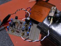
With 10ohm source resistors the voltage on the positive sources was 58mv, the negative was -80mv. With the two jumpered both sources were at -20mv, which points to the need for the resistors as you stated. No need for a ground referenced offset adjustment if the fets are matched in the same ballpark.
I have more questions, but I'm tired and it'll wait until I can place them in a coherent form.
Thanks for your comments. I feel like I'm going back to basics just to make sure I really understand how these work.
Mike.
Attachments
Charles Hansen said:So you are not using source resistors in the BT?
john curl said:Yes, Charles, I am using 10 ohms per device, but that is a special topology, just like yours.
Without going further in design details, what are the particularities and advantages of such a special configuration compared to the classic fet complementary differential pair?
john curl said:Mike, you seem to understand it completely, now.
Hi John,
It can take a bit but I come around eventually.
I have one more grey area concerning Vgs that I hope you won't mind adding to my understanding.
In a MC preamp input stage my thought would be that I need a Vgs somewhere below .5v (.1v ?) and I have noted from sorting fets (and from the spec sheets) that the Vgs range drops with lower Id biasing. You have indicated that operating fets at just below Idss is best and that there are negatives to biasing them lower.
My question is, am I correct in determining a low Vgs is needed for a MC cartridge out level, or is a fet's response to this low level input still linear with a Vgs of say 1V? I want the best resolving of low level details in the groove. So I'm drawing a knee jerk conclusion that it is. Also, if it is necessary, is biasing for a lower Id/Vgs a wrong approach and I need to find different fets. I just bought a bunch of 2SK170/J74s.
Regards, Mike.
Please let me know if this is too far off topic here.
Regards, Mike.
Justcallmedad, I just meant the complementary differential folded cascode, first done by Charles Hansen in a production product. This circuit topology requires MORE from the input, because the output current IS the input current. This is NOT true with the JC-80 or Levinson designs.
john curl said:Low Vgs means BOTH high Gm and low Idss. It doesn't really matter what the exact range of Vgs is, but it is best to run the devices near Idss to get lowest noise.
Thanks John. I suppose that I'll just sort the fets I have with this in mind and see what happens.
Time to get some boards built.
Mike.
Charles Hansen said:
So you are not using source resistors in the BT?
john curl said:
Yes, Charles, I am using 10 ohms per device, but that is a special topology, just like yours.
Justcallmedad said:
Without going further in design details, what are the particularities and advantages of such a special configuration compared to the classic fet complementary differential pair?
john curl said:Justcallmedad, I just meant the complementary differential folded cascode, first done by Charles Hansen in a production product. This circuit topology requires MORE from the input, because the output current IS the input current. This is NOT true with the JC-80 or Levinson designs.
John, my last post was not really clear (sorry) my question refers more specifically to the input stage and your particular fet inputs arrangement "but that is a special topology" : source resistors/gate inputs, and not to the well known now, folded cascode design. I am just curious to know the advantages of such input scheme vs. the "classical" fet complementary differential input configuration.
Low Vgs means BOTH high Gm and low Idss. It doesn't really matter what the exact range of Vgs is, but it is best to run the devices near Idss to get lowest noise.
Low Vgs means low Vgs. Low Vgs doesn't mean low Idss/high Idss. It is not very practical to run the device near Idss to get lowest noise, as doubling of Id means square root of two lower Gm or 3db better SNR for stand alone JFET
- Status
- Not open for further replies.
- Home
- Amplifiers
- Solid State
- John Curl's Blowtorch preamplifier