John, thanks for the jfet+R||C voltage reference tip. I have been using this for a little while with excellent results. I'm glad to have arrived at this solution (using j201) independently and to see it here confirmed by you.
There's still something that confuses me. You've said clearly that you're using separate regulators for each stage and channel. I can only think of one reason to do that, to avoid cross modulation. But in the same time just a few pages ago you told me output impedance isn't important. To me this doesn't add up, unless, what you mean is that the output impedance is important only if multiple circuits get fed from the same regulator (they'll modulate each other's supply) but that individually self modulation isn't affecting the sound.
Obviously you've built the thing and it must have been the best solution for the sound you wanted, so I'm sure you have your reasons for doing it this way, I'm just trying to understand it, that's all.
Separated are a MUST.
Yes, Pavel, but why?
Here's my guess. Because of the not so low output impedance of each regulator. John specifically said that he avoids using a capacitor in the jfet+R voltage reference (in part one of this thread) because it influences the sound. Not using a capacitor in the voltage reference, in my circuit, greatly increases the output impedance. And then sure, with high output impedance one must at least have several separate regulators, to avoid cross modulation. The same high output impedance which would result in cross modulation if not using separate regulators SHOULD affect even each stage powered by the individual unit. But both you and John are telling me it doesn't. What am I missing?
Ikoflexer, you have it almost right.
In the early Levinson JC-2, we used a simple cap multiplier to lower the noise coming from the commercial +/- 15V supply, that we were using. The power supply noise was OK for the line stage, but the phono stage needed it. We paralleled the left and right channel. This seemed OK for more than one year of production, when both Mark's engineer and I, separately, realized that the finite output impedance (perhaps 4 ohms, I can't remember for sure) was causing the two channels to interact in some subliminal way and we were losing stereo image. Mark chose to have his engineer make a super regulator, with a very low impedance, to replace the cap multiplier. I would have chosen parallel cap multipliers, but that was not retrofittable in the existing Mother-board that Mark designed for the JC-2, so it was not used.
I found out separately, because I was developing a multichannel mixing board in Switzerland for a recording studio and we had tried to parallel 8 channels on a single cap multiplier. Big mistake and easily measurable.
IF the output resistance is reasonably linear, and it is, if the load is Class A, then little harm is done. However, paralleling different channels, allows for a subtle form of x-talk, that is not good. ALWAYS put a large cap across the V setting resistor in the Norton equivalent Zener reference. However, I did not put a large cap at the OUTPUT of the fet follower that the Zener reference controlled. This is a separate issue, entirely.
Last edited:
Thank you John! Much appreciated. I've been doing many experiments lately on a particular regulator design and what you just said is aligned with my findings. As being relatively new to all this, it is comforting to get confirmation especially from some one of your experience. 
Last edited:
Ever onward, we have a selection of series pass devices to use. Each has advantages and disadvantages. I tend to use mosfets for higher current applications and jfets for low noise applications. Bipolar transistors can be fairly quiet and less lossy, but they have other problems.
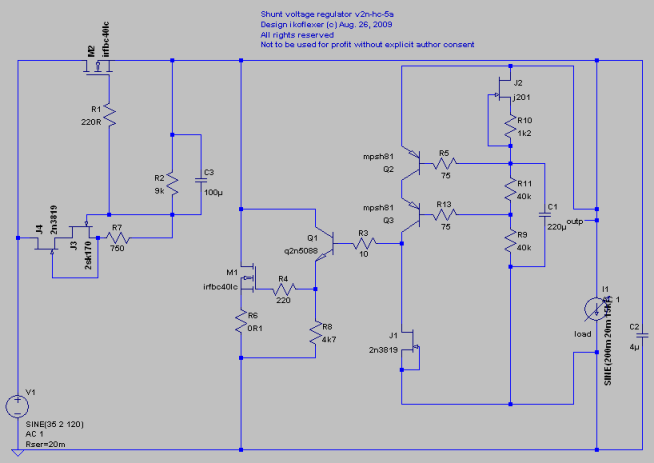
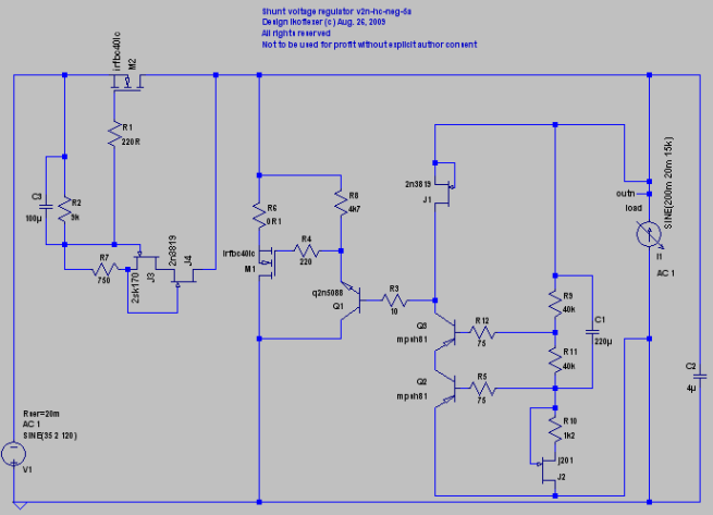
John, it might be easier to make comments on an example, and I know you don't publish schematics. Here is what I've been experimenting with, the target being DACs, headphone amps, or power amps (for those who don't mind huge heat sinks). So far I've tested it with some very nice results up to about 4A (20V out). The parts values shown should be taken only as indicative of the real parts, not an exact match. Because it's not targeted specifically at a particular circuit, I wanted it to have low output impedance, low noise, and very good psrr. I already got more ideas from you about psrr, so In the future I'll probably use a few regs in series for best psrr. However, the last regulator I'm thinking about shunt, as you see below.
After you shook me a bit the other day I went and read the first 200 pages of the BT part one thread. I'm very glad I did.
Back to your comment about about choosing bipolars or mosfets. In the past you noted that you prefer to use an all jfet+mosfet circuit. I know this might be boring and old news for you, but since you said you wanted to teach us something, I'm soliciting your attention. Would you recommend to get rid of the bipolars in the circuit shown below?
may be also between the emitter of Q1 and ground.
That would certainly improve the performance

That would certainly improve the performance
Ovidiu, for everyone's benefit, can you please expand ?
") (I do know that a cap from the emitter of Q1 to ground messes up Zout in a big way.)
(I do know that a cap from the emitter of Q1 to ground messes up Zout in a big way.)Joshua, thanks for the suggestions; as I said, anything that has to do with the passive parts is left as a tweaking exercise; I'm referring to resistor values, bypassing large caps with smaller ones, etc.
Any comments on the use of bipolars in the control loop?
Fair enough. To be honest I have no idea what technical concepts are or are not acceptable in this thread. There were quite a few good lessons for me in part one of this thread, I hope part 2 gets on track.
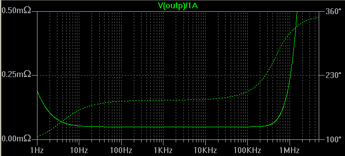
And before anyone bangs me over the head with it, as a disclaimer I'll say that I'm fully aware that such output impedance plots are only simulations and belong in the fantasy land of wishful thinking
And before anyone bangs me over the head with it, as a disclaimer I'll say that I'm fully aware that such output impedance plots are only simulations and belong in the fantasy land of wishful thinking
Ovidiu, for everyone's benefit, can you please expand ?
I believe he meant slowing down the parallel regulation action.


 SOS!
SOS!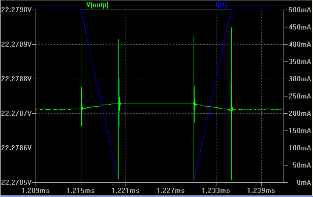
Ikoflexer, I must be getting old (and I am) but I am having a hard time analyzing any subtle properties of what you have designed by inspection. Joshua's input while well meaning, is ambiguous, because paralleling a high Q cap can cause more ringing. We usually put our high Q caps next to the load, rather than in the regulator section.
Syn08 hasn't offered any input as of yet.
Syn08 hasn't offered any input as of yet.
Syn08 hasn't offered any input as of yet.
Unfortunately, that is entirely correct.
Syn08 hasn't offered any input as of yet.
Sometimes criticism may be helpful, though only sometimes.
What often matters is WHY criticism is given. If it is given to correct a potential oversight or even a mistake, then it should be acceptable. If it is given as a put-down, without any redeeming value to anyone, then it is useless and potentially harmful.
It is not always easy to accept criticism or even give it tactfully. I am certainly accused of hurting people's feelings on this thread, over the years. I have never deliberately done so, except to put someone in their place, when they were trying to override me for their own reasons, but it surely lingers with some people. I usually call this 'negatively sensitive' or biased to ones own feelings without regards to the feelings of others in the debate.
Surely, everyone has experienced this, when someone, for some reason, runs rough-shod all over you and if you say something back in your own defense, even, they get their feelings hurt, and indefinitely hold a grudge.
It happens here, all the time.
What I am trying to convey with this basic discourse on power supply design and regulation, is NOT specific circuits, but the tradeoffs in various approaches, when it comes to audio design.
Many of these simple circuits are not really adequate for DC instrumentation, etc, as they are not DC stable enough, but audio is not a DC signal, so it is often possible to use simple, no, or low feedback regulators with great success.
Last edited:
- Status
- Not open for further replies.
- Home
- Member Areas
- The Lounge
- John Curl's Blowtorch preamplifier part II