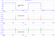
Well, we may say that Blowtorch-like circuit has pretty constant supply current in both rails:
Thank you Pavel, you just saved me a couple hours of unpaid work
")
The simple linear regulators are used with each Blowtorch line stage, as well as the Vendetta Research phono stage inside the CTC Blowtorch. In fact, a total of 12 simple linear regulators are used in a Blowtorch with a phono stage. This is why we are discussing simple linear regulators.
It is true, and it can be noted by inspection of the schematic, that the 4 quadrant line stage presents a constant load to the linear regulators that supply it. However, virtually all class A symmetrical designs do much the same thing. It is only class B designs that change load current in a serious way, and even they constantly load the regulator with a constant current demand from the input and second stages that do run class A.
Anyone who wants to copy one of my designs, either from the early Levinson JC-2, the new Parasound JC-2, or the CTC Blowtorch, will do well to use simple linear regulators with every gain block.
I should clarify a few points before going forward:
Simple voltage regulators have existed in audio and instrumentation since the very beginning of electronics design, at least 75 years. It is only the parts that have really changed. In the beginning, there were power tubes used as series pass devices, and gas tubes instead of Zener diodes. Yet, the TOPOLOGY was the same as we are discussing here. The loads, then, as my circuits are, today, were mostly class A, and therefore not a problem.
PMA has shown a potential problem that is not really practical in nature, and is addressed in the actual construction of the simple linear regulator.
First, there is no 'infinite' rise-time in audio. I defy anyone to find a serious rise-time significantly faster than 10us in any listenable music source. The 1/2" or more diameter microphones won't do it, SACD won't do more, 30 ips analog tape won't do more, etc. Check it out for yourself. This being said, the switching transients shown by PMA are exaggerated in their significance. Also, it must be remembered that simple voltage regulators always should have a cap of .1-100uF on the output, between it and the load. This tends to 'fill in' on transient current needs. Please note this everyone.
So, the lesson to take home is? Simple regulators (most likely a series pass element design) will suffice for most cases. How about the cases that need something better? How would you describe those cases, and what would the specs for an adequate regulator be? I'd like to add that the target is ultimate sound, not just average. For that we can use an lm317 and call it quits. I'd also like to add that we should assume that one is not willing to cut corners, not even if it means large current consumption (such being the case for shunt regulators).
If this is too boring and not high end enough, please point to the source of info where those of us who don't have the answer should chase.
If this is too boring and not high end enough, please point to the source of info where those of us who don't have the answer should chase.
You are missing the point, Ikoflexer. I use LM 317's and LM 337's in EVERY DESIGN that I make, BUT they are not directly connected to the audio circuits, without simple linear voltage regulator buffers, in EVERY gain block. There is no, one, perfect voltage regulator. That is why I use 3 in series for the CTC Blowtorch. Each has its advantages. The LM devices filter the hum and set the voltage. The discrete shunt regulator snubs power supply transients and adds a constant load to the IC series regulators. The discrete linear voltage buffer, further reduces the transients from the power supply, and can lower the noise, if necessary.
You are missing the point, Ikoflexer.
Maybe I am, but I don't see what points are to be missed. I thought this was a discussion. Many points.
I use LM 317's and LM 337's in EVERY DESIGN that I make, BUT they are not directly connected to the audio circuits, without simple linear voltage regulator buffers, in EVERY gain block. There is no, one, perfect voltage regulator. That is why I use 3 in series for the CTC Blowtorch. Each has its advantages. The LM devices filter the hum and set the voltage.
OK, so I'm talking a risk here by talking about it without seeing the schematic (I've searched for anything resembling a blowtorch schematic without success).
Is the noise introduced by the LMs not a concern? Or whatever comes after the LMs does the extra filtering?
The discrete shunt regulator snubs power supply transients and adds a constant load to the IC series regulators. The discrete linear voltage buffer, further reduces the transients from the power supply, and can lower the noise, if necessary.
Can you give us an idea of the psrr vs. frequency achieved by this series of three setup? I'm not going to ask about Zout since, as you said above, that is something not to worry about in this case. I know you can say the psrr is good enough and the sound is the proof, but there are engineers in the audience, and they like numbers. I'm not an engineer, but having never listened to one of your devices, I'll settle for a number/plot.
And please do not take my questions as challenges, although that might be more on your liking. I think there is a large number of people reading these threads that can learn from your comments, myself included.
You must do your own calculations. It is not that important to me.
However, of course, the LM317/337 combination is noisy. That is why we designed simple linear voltage regulators, or cap multipliers into the circuits in the first place. The simple voltage regulators can be quieter than the LM devices and they do not suffer from transient overshoot. However, there are more sophisticated versions of simple series pass regulators that we had not yet addressed in the last few days, but in the Blowtorch 1 thread, were shown by others, other than me.
However, of course, the LM317/337 combination is noisy. That is why we designed simple linear voltage regulators, or cap multipliers into the circuits in the first place. The simple voltage regulators can be quieter than the LM devices and they do not suffer from transient overshoot. However, there are more sophisticated versions of simple series pass regulators that we had not yet addressed in the last few days, but in the Blowtorch 1 thread, were shown by others, other than me.
Last edited:
I might be helpful here to address Ikoflexer's PSRR question, in general, but not specifically, as each situation is different.
For example, the LM317 has lots of hum reduction, or high PSRR at 50-60 Hz, but is next to useless at 1MHz or more. A power line has 50MHz or more on it, in many cases. What to do? The linear regulator, especially the cap multiplier might have only 20 dB or PSRR at 60Hz, but maybe 40-60dB between 1K and 10MHz. See what happens when you put them in series? Add them up.
For example, the LM317 has lots of hum reduction, or high PSRR at 50-60 Hz, but is next to useless at 1MHz or more. A power line has 50MHz or more on it, in many cases. What to do? The linear regulator, especially the cap multiplier might have only 20 dB or PSRR at 60Hz, but maybe 40-60dB between 1K and 10MHz. See what happens when you put them in series? Add them up.
Wild guess: the two LMs, do they add-up to behave like a big choke?
Jim Williams has some nice pics of lowering RF spikes with strategically placed ferrite beads. This is the context of his LDO switching regulators.
(John, and I apologize for my earlier knee-jerk reaction.)
Edit: besides the trivial conclusion that one of the LMs trims all the low frequency hum, while the second gets rid of the high frequency psu artifacts.
Last edited:
Joshua_G,
The first step in engineering is often to clearly define the problem. You asked about a specific regulator circuit. Obviously it is not the best choice for many applications, but could be great for others.
Elegance in engineering is providing a good or excellent solution using few parts or what appears to be a simple design.
One of the first issues to be defined in a regulator circuit is "What is the input voltage?"
In the US the AC line voltage is slowly being changed. It is raised every few years to allow for more efficient transmission. Today 129 volts can be provided from a standard single leg, single phase outlet. It can also be 108 volts and still in compliance. There can also be harmonic distortion to the peaks of the sine waves resulting in another 5% loss of peak voltage. So the actual range can be 145 to 184 peak volts. This is scaled down by whatever power transformer that is used.
Of course the transformer also has some internal losses that vary with load.
The normal practice is to use the lowest possible voltage for the design value and then check again at the highest voltage to make sure the parts are not overstressed or getting too hot.
The next issue you may want to look at is the load requirements. What voltage range is required, how much current and what is the sensitivity of the load to variations in voltage.
You probably want to design for twice the expected current. Then be sure to check and see if a short circuit will damage any components. Often a surge from the filter capacitor thought the series pass transistors base will cause a failure resulting in high unregulated voltage passing after the short clears. A very bad result.
As some with good hearing can hear signals as low as - 10dba and some with hearing loss may actually withstand 145dba there is 155db dynamic range right there. Allow for some listeners close to the loudspeakers and some far away you might want to allow even more dynamic range, also consider that one may not properly match a pre-amplifier's signal level properly to the power amplifier and you may have to allow as much as 20db more for that.
I used to design for 140db range, but I think these days 160 or more is needed for the best quality. This is an engineering judgment.
If the stages you are driving have good power supply rejection ratio's then the regulator can be simpler. If you are using many of the circuits that have been shown in these threads you may want to go with a more complex route.
Some use a pre-regulator to condition the voltage to reduce the demands on the final regulator. That is one design option.
Other may use high gain active devices to increase the feedback to achieve better regulation. That is another approach.
You can also use a bridge circuit to minimize the power supply importance, a third method.
In the simple regulator you asked about, under the right conditions it is a real winner. A couple of details will help you.
Zener diodes are modeled as perfect voltage shunts with a series resistance. It would be logical to assume the series resistance for a 10 volt diode is twice that as for a 5 volt unit. It is not. The lowest resistance occurs in diodes with values from 5.6 to 6.8 volts, depending on type and manufacturer. The 6.8 volt values often have the best thermal stability. When you use several diodes in series, the noise level increases by the square root of the number of diodes, so it often is less than if you used a single diode of higher voltage. So for most hifi voltages use two or three diodes in series.
There is also an optimum current for the diodes to have the best results, a quick look at a good data sheet will show current vs voltage. Look for the most linear part of that curve for a starting point.
Capacitors can create small voltages when they are vibrated. There is a base level of vibration of .005 G's or more in most locations. Electrolytic capacitors are internally damped by the electrolyte. They are very good for reference voltage filters. All capacitors can have the vibration voltage minimized by mounting them so they have the smallest footprint possible.
Some resistors, notably carbon composition also have vibration induced noise.
The resistor from the zener to the capacitor should be sized to allow a balance between regulation and noise reduction. This can be calculated if you can estimate the ripple to the zener, approximate the zener's resistance, know the load current and the gain of the series pass transistor.
You can actually estimate the optimum gain for the pass transistor from the same data. Usually higher is better but that will often trade off with bandwidth and stability.
One big issue to watch is the inductance in the emitter lead, too much and the circuit can oscillate. The same can occur if the output filter film capacitors are wound with a high inductance design.
Of course be sure the parts all can take the heat, although 2 to 1 is the usual margin you may wish to go to 3 or 4 to 1.
These are just a few of the issues for your regulator question.
It is correct that multiple series regulators work better, usually, than a simple series regulator, for most audio applications. However this also implies that you have some extra voltage to throw away. If you don't then things get more difficult.
In fact, Zener diodes are often not a good way to go. They are VERY noisy, in general, for any voltage above 6V.
Still, we sometimes need a voltage reference that is quiet. This can be made with a low noise fet used as a current source, a resistor to set the voltage, and a large cap to short out the voltage and current source noise. This is called a Norton equivalent to the Zener diode and series resistor. It works very well, but it takes a bit of resistor adjustment to get the voltage right.
- Status
- Not open for further replies.
- Home
- Member Areas
- The Lounge
- John Curl's Blowtorch preamplifier part II