That's OK, as long as we keep looking, maybe we'll find something new.
In any case, you will love this -
The elimination of the resistor to ground did little to alter the results.
What did make a difference was precisely compensating for the amplitude
and phase shift between the input and output fundamental.
The result was a fairly pure second harmonic which looks like the
degenerated case. I don't doubt that there is some 3rd lurking down there
somewhere, but you can't see it visually - it's certainly a lot less than
Baxandall's curve.
I went back and looked at some of my old actually measured data
for Fets. 10 dB of degeneration created 3rd harmonics that were about
30 dB down from the 2nd, which is consistent with what I have here.
If you look at the Baxandall/JLH curves, they show about 12 dB down.
Of course I believe they were using bipolar devices, not fets.
for Fets. 10 dB of degeneration created 3rd harmonics that were about
30 dB down from the 2nd, which is consistent with what I have here.
If you look at the Baxandall/JLH curves, they show about 12 dB down.
Of course I believe they were using bipolar devices, not fets.
Last edited:
Hi Nelson,
Have you tried eliminating the effect of the input capacitance of the fet - in the degenerative case, this works against the 0.31 soource resistor but in the loop case it is working against 360R. I think you'l find that this is a major contributor to the difference!
Alex
Have you tried eliminating the effect of the input capacitance of the fet - in the degenerative case, this works against the 0.31 soource resistor but in the loop case it is working against 360R. I think you'l find that this is a major contributor to the difference!
Alex
The 'idealized' number for second harmonic null with a single bipolar transistor is 1/2Gm.
However, given a typical input drive impedance it could change to something lower. It is not much local negative feedback, in any case. So for 1ma, it would ideally be 13 ohms, or for 0.1ma, it would be 130 ohms. [Class notes, 1973, D.O.Pederson and R.G.Meyer, standardized class notes for Nonlinear Circuit Analysis, UCB, p.192 ] Also, 'Analog Integrated Circuits for Communication' Donald O. Pederson, Kartikeya Mayaram, Kluwer Academic, 1991 p.111
However, given a typical input drive impedance it could change to something lower. It is not much local negative feedback, in any case. So for 1ma, it would ideally be 13 ohms, or for 0.1ma, it would be 130 ohms. [Class notes, 1973, D.O.Pederson and R.G.Meyer, standardized class notes for Nonlinear Circuit Analysis, UCB, p.192 ] Also, 'Analog Integrated Circuits for Communication' Donald O. Pederson, Kartikeya Mayaram, Kluwer Academic, 1991 p.111
Last edited:
I did that by taking the frequency down to where it didn't make a
substantial difference, confirming that with a phase plot that hit
180 deg (it is an inverting amplifier) very accurately.
BTW, the IRF450 used was simply a stock model provided by MicroCap.
You should be able to use just about anything to explore these issues
(as long as you use the same part)
substantial difference, confirming that with a phase plot that hit
180 deg (it is an inverting amplifier) very accurately.
BTW, the IRF450 used was simply a stock model provided by MicroCap.
You should be able to use just about anything to explore these issues
(as long as you use the same part)
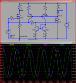
again with showing how to get "the same" response as degeneration with "loop feedback"
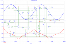
this time I used power Mosfet to be closer to Nelson's sim, actually used "real parts" to measure, transfer, float the feedback in series with the M2 gate across the 50 Ohm R5
the waveforms, distortion profile match very well: the "big" (ie visible) 2nd harmonic diff is ~0.9dB
the "real" input current for the M2 circuit is dominated by the bjt mirror errors
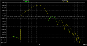
a "curious" behavior is that the Ltspice included IRFP240 model gives a deep notch for the 2nd harmonic in M2's output - which goes away when the supply
V is boosted to 200 V - I wouldn't think the small Vds AC difference due to the degen R would have an obvious effect
this time I used power Mosfet to be closer to Nelson's sim, actually used "real parts" to measure, transfer, float the feedback in series with the M2 gate across the 50 Ohm R5
the waveforms, distortion profile match very well: the "big" (ie visible) 2nd harmonic diff is ~0.9dB
the "real" input current for the M2 circuit is dominated by the bjt mirror errors
a "curious" behavior is that the Ltspice included IRFP240 model gives a deep notch for the 2nd harmonic in M2's output - which goes away when the supply
V is boosted to 200 V - I wouldn't think the small Vds AC difference due to the degen R would have an obvious effect
Attachments
Last edited:
a "curious" behavior is that the Ltspice included IRFP240 model gives a deep notch for the 2nd harmonic in M2's output - which goes away when the supply V is boosted to 200 V - I wouldn't think the small Vds AC difference due to the degen R would have an obvious effect
Given that the load is fairly high impedance, I think you were seeing the
load-line cancellation of 2nd harmonic - the variation in gain due to Vgs
cancels that of the Vds, also known as the "sweet spot". At higher voltage
that point will correspond to a somewhat higher load impedance and vice
versa (IIRC).
Last edited:
Scott,
Using a local feedback loop around the VAS will reduce the VAS's distortion (as will degeneration.
As for output stages and crossover distortion et al we can debate endlessly, outside the "commodity" commercial arena the "easy eay out" is to use larger heat sinks, bigger power supplies, more output devices and more quiescent current, combined with a smidgen of feedback around the output stage (or not) to reduce the GM doubling distortion.
In the light of the levels of distortion in Microphones and speakers I cannot loose sleep over a few fractions of a percent 2nd HD and even less 3rd HD, which is what competent design gets you.
Ciao T
Not addressed by that connection either, a story for another day.
Using a local feedback loop around the VAS will reduce the VAS's distortion (as will degeneration.
As for output stages and crossover distortion et al we can debate endlessly, outside the "commodity" commercial arena the "easy eay out" is to use larger heat sinks, bigger power supplies, more output devices and more quiescent current, combined with a smidgen of feedback around the output stage (or not) to reduce the GM doubling distortion.
In the light of the levels of distortion in Microphones and speakers I cannot loose sleep over a few fractions of a percent 2nd HD and even less 3rd HD, which is what competent design gets you.
Ciao T
Hi,
No, it is like telling the overeager pupil "You got an F because you essay was not on topic.". I am aware of your point, but it is not relevant to the debate. So I do not need to look into your reasoning, but you need to look into Nelson's reasoning...
Ciao T
not looking into the reasoning behind by sim is sort of like telling your 1st year physics teacher to "stuff it" because point masses, infinitly rigid, massless beams, perfect fulcurms don't exist
No, it is like telling the overeager pupil "You got an F because you essay was not on topic.". I am aware of your point, but it is not relevant to the debate. So I do not need to look into your reasoning, but you need to look into Nelson's reasoning...
Ciao T
Hi Nelson,
I wonder if I could some more into your seaside time (I hate it when someone does that to me, so do not feel obliged)?
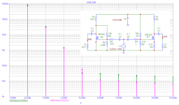
Would it be possible to tweak the circuits so that the two feedback cases have excactly 10dB Feedback, drive each circuit so it produces exactly 10V PP and to then show an FFT of the output at 100Hz, 1KHz, 10KHz and 100KHz, even 1MHz if possible (if the circuits have enough bandwidth)?
This may make things clearer than showing the distortion residual.
Ciao T
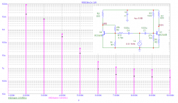
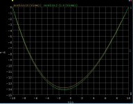
I took my loop feedback example down to 10 Hz to remove most of the phase delay, and here is the resulting waveform. You can see the 3rd harmonic compression more clearly.
I wonder if I could some more into your seaside time (I hate it when someone does that to me, so do not feel obliged)?
Would it be possible to tweak the circuits so that the two feedback cases have excactly 10dB Feedback, drive each circuit so it produces exactly 10V PP and to then show an FFT of the output at 100Hz, 1KHz, 10KHz and 100KHz, even 1MHz if possible (if the circuits have enough bandwidth)?
This may make things clearer than showing the distortion residual.
Ciao T
Hi,
Interesting. How "real" are these models?
Also, could we make both either 10dB or 25dB Gain, not two different ones, so we compare as much as possible equal systems?
As it stands, it is hard to say why the differences fall the way the do, between BJT and FET. I have my suspicions, but rather see more data...
Ciao T
Some simulations with MOSfets and low power bipolar transistors
Interesting. How "real" are these models?
Also, could we make both either 10dB or 25dB Gain, not two different ones, so we compare as much as possible equal systems?
As it stands, it is hard to say why the differences fall the way the do, between BJT and FET. I have my suspicions, but rather see more data...
Ciao T
Drain-gate feedback is exactly the same, in that 'outside' you can't tell how much of the reduced output impedance is due to the device and how much from the feedback. That is the nature of a 'black box' - you are not allowed to look inside it.Chris Hornbeck said:The same charge flows through the cathode/emitter/source and through the degenerating resistor. It's not possible to distinguish, from the "outside", how much resistance is inside the active device and how much is a separate resistor.
It's not that degeneration escapes causality, but rather that causality happens to the degenerated device as a single step in the causality chain.
In both cases you also get a change in input impedance, but you can't tell from outside the box what is causing this. I think your 'metaphysics' argument is a red herring.
I can't see the mistake in my original power series calculation, but I have just flogged through the proper calculus and now find Re=1/2gm. Apologies.john curl said:The 'idealized' number for second harmonic null with a single bipolar transistor is 1/2Gm.
No, not in the JC-3 circuit. I plotted the DC voltage transfer function, the case with the two 1Meg feedback resistors (500k) is ever so slightly worse because the VAS has to supply their current. I used the Barrie Gilbert method of forcing the output and plotting the input. BTW .7ppm linearity (albeit DC).Using a local feedback loop around the VAS will reduce the VAS's distortion (as will degeneration.
Ciao T
I used very ordinary devices, SK170/J74, 2N4401/03 biased a 3-5ma in all the devices.
Degeneration is inside the driving gm and modifies the transfer function not the same thing.
Applying 10mV signal to an openloop op-amp and observing a distorted output, then applying a 40dB feedback network and observing a nice 1V signal at the output is not "broadbanding and linearizing". The op-amps transfer function has not been modified.
Resistor feedback from the high-z node to the bases of the two VAS transistors did nothing either (to the OVERALL transfer function).
Attachments
Scott,
I am not sure why you would come to this conclusion, it may be your models or your method. I am not quite sure that your method of "forcing the output" is valid for this case.
I do not have the time to analyse this for this particular case, I have done similar analysis on an amplifier using two series differentials and there it is certainly true, I cannot see why the same should not hold for the JC-3.
Ciao T
No, not in the JC-3 circuit.
I am not sure why you would come to this conclusion, it may be your models or your method. I am not quite sure that your method of "forcing the output" is valid for this case.
I do not have the time to analyse this for this particular case, I have done similar analysis on an amplifier using two series differentials and there it is certainly true, I cannot see why the same should not hold for the JC-3.
Ciao T
Some simulations with MOSfets and low power bipolar transistors
These comparisons are only valid in situ. The source and load impedance interactions are not the same. In circuit there are no ideal generators except at the input and then only in simulation. Note the subtle complexities of Middlebrook's work on really breaking a feedback loop.
No, not in the JC-3 circuit. I plotted the DC voltage transfer function, the case with the two 1Meg feedback resistors (500k) is ever so slightly worse because the VAS has to supply their current. I used the Barrie Gilbert method of forcing the output and plotting the input. BTW .7ppm linearity (albeit DC).
Degeneration is inside the driving gm and modifies the transfer function not the same thing.
Applying 10mV signal to an openloop op-amp and observing a distorted output, then applying a 40dB feedback network and observing a nice 1V signal at the output is not "broadbanding and linearizing". The op-amps transfer function has not been modified.
Scott,
Bad sign, I think we agree on this!
A while back I asked a theoretical question about local versus global feedback. I thought that was at the high school algebra level. So let's try a simpler version. If I have two distortion generating circuits and the distortion of one is X but bound between 1 and 100 and the second stage is 100 - X, what value of X yields the lowest distortion? X * (100-X) = ?
ES
- Status
- Not open for further replies.
- Home
- Member Areas
- The Lounge
- John Curl's Blowtorch preamplifier part II