I am not quite sure that your method of "forcing the output" is valid for this case.
Ciao T
You mean PIM might not exist afterall!
 It was not necessary but it makes an easier comparison, two circuits at exactly the same output what are the inputs. The reverse is easily computed.
I think your 'metaphysics' argument is a red herring.
Metaphysics? Seems a little harsh - Arf! You may very likely turn out to be right that a classic loop model applies to degeneration exactly, or it may turn out that the Baxandall/JLH/Putzeys interaction will not occur. Hopefully we'll have an agreed upon test before long and clear this up.
I'm sorry if my posts about this seem like semantics. To me, they've been about choosing the correct model.
Thanks,
Chris
X=1 or 99. The highest distortion comes from X=50.simon7000 said:what value of X yields the lowest distortion? X * (100-X) = ?
As I said, algebra (and/or calculus) shows this. Just do the math! The 3rd order cancellation which John Curl and I were discussing is a good example. The 3rd generated from interaction between intrinsic 2nd and 2nd from the feedback happens to be the opposite sign from that of the intrinisic 3rd for a BJT. If you can't or won't do the sums yourself then you will just have to trust those who have. Sorry to be blunt, but we don't need a test to prove that maths actually works! However, for the doubters see this article, which does the sums (in a slightly unhelpful way) then reports actual measurements which confirm the theory.Chris Hornbeck said:You may very likely turn out to be right that a classic loop model applies to degeneration exactly, or it may turn out that the Baxandall/JLH/Putzeys interaction will not occur.
my big post on modeling the JC-3 inner loop feedback http://www.diyaudio.com/forums/anal...ch-preamplifier-part-ii-1581.html#post2705814 was apparently largely ignored – 2 downloads?
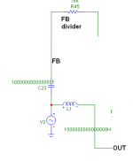
it is a abstract, spice sim but I claim it does follow the JC-3 topology and is sufficient for addressing this question of what does the inner loop feedback do for the circuit via any "reduces the drive impedance to the output stage" heuristic
Bode sensitivity analysis shows next to no effect from the "inner loop" on current disturbance at node "x" in my sim which is equivalent to the EF driver Q input, "VAS" interface node
this sensitivity analysis “disturbance current” could be tweaked to follow expected load current/hfe induced base current at this node
but considering it an independent source we can just plot the response of the amp and compare with the local feedback in place or disabled
the plot is really boring - no difference (33mdB difference on 30+ dB base ) with and without the inner feedback R (swap B1 and Ierror, do AC analysis, look at Vout - asc in long post linked above)
Attachments
Last edited:
X=1 or 99. The highest distortion comes from X=50.
Well since you are the only one playing the game, you win the grand prize! Just send me $50.00 for shipping and handling charges and it will be on it's way to you!
So you pretty much seem to have a grasp of local vs. global feedback (and not degeneration as we are calling it here) advantages and disadvantages.
Multiple gain stages can when well controlled provide some cancellation. Get your inside the loop gain from the lowest distortion stage for the best overall results. High distortion stages are best handled locally.
The important point is that you must include the error in every stage when doing a feedback distortion calculation. Allowing for a single (even very complex) term to show the error may be technically correct but masks the real issues.
Last edited:
Note the subtle complexities of Middlebrook's work on really breaking a feedback loop.
You mean something like this?
Attachments
the distortion cancellation condition is not robust to real device production spread Vt, gm variations will require you to trim tubes, fets - maybe where bjt Vbe exponential diode model determines distortion you could have a chance of making the (single) harmonic cancellation work
a more robust winning strategy is to put more gain in the loop, possibly using local feedbck to permit global stability (eg Lin 'op amp" topology Cdom Miller feedback, with "beta enhancement")
diff pair, complementary push-pull followers are probably the 2 most used "distortion cancellation" schemes
Last edited:
I am happy to donate my prize to charity! However, I have absolutely no idea what this little sum has to do with distortion.
"The important point is that you must include the error in every stage when doing a feedback distortion calculation. Allowing for a single (even very complex) term to show the error may be technically correct but masks the real issues."
I'm not sure I understand what you are saying here. Something can't be "technically correct" and yet wrong at the same time. The art in science and engineering is to choose the right level of abstraction and approximation.
Last edited:
I am happy to donate my prize to charity! However, I have absolutely no idea what this little sum has to do with distortion.
"The important point is that you must include the error in every stage when doing a feedback distortion calculation. Allowing for a single (even very complex) term to show the error may be technically correct but masks the real issues."
I'm not sure I understand what you are saying here. Something can't be "technically correct" and yet wrong at the same time. The art in science and engineering is to choose the right level of abstraction and approximation.
Did you read the Linear Audio Vol 1 article on feedback? He uses a single error term even with two gain stages but allows it to be as complex as you want. So you can't actually say the derivations are wrong, just incomplete.
my big post on modeling the JC-3 inner loop feedback http://www.diyaudio.com/forums/anal...ch-preamplifier-part-ii-1581.html#post2705814 was apparently largely ignored – 2 downloads?
it is a abstract, spice sim but I claim it does follow the JC-3 topology and is sufficient for addressing this question of what does the inner loop feedback do for the circuit via any "reduces the drive impedance to the output stage" heuristic
Still probably to esoteric for most. We've already been told that the output stage distortion does not matter so why reduce the drive impedance to it anyway? I don't expect an answer as to why a basic .7ppm transfer non-linearity of the VAS is the dominant distortion mechanism either.
Last edited:
John, Thorsten and other designer who prefer low or no feed-back designs: what type of feed-back do you think is acceptable for the best sounding amplifiers ?
Here are the types of feed-back in decreasing order of "strength":
-global feed-back
-local feed-back (not including degeneration)
-degeneration (local)
I suppose the global feed-back is to be avoided in the best sounding amplifiers, and the degeneration is acceptable. That leaves the local feed-back: is is acceptable or should it be avoided where possible ?
It is a good method. The AD797 has this solved.
Round and round it goes.
I think you posted this the first time on april 20th 2009.
BTW: I have a bad memory.

OK one more.
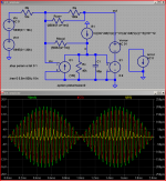
I had time for one more example. So now I made a complete little JC-3 by adding a simple EF output and only making it drive the 80K feedback resistor.
I also fiddled with the input sin wave so with/wo the inner loop the output was exactly the same.
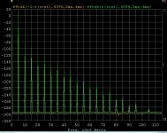
Same answer down to double precision noise. The inner loop is ~1dB worse because is has to drive the 1M resistors (extra 10uA peak). I also did this at 5kHz to bring into play all sources of distortion in the VAS. Don't be fooled by the resolution the worst harmonic is <-100dB. Our simulator has a feature for getting -300dB noise floor, others might too but some don't.
Brought to you by the objectivist tag team.
I had time for one more example. So now I made a complete little JC-3 by adding a simple EF output and only making it drive the 80K feedback resistor.
I also fiddled with the input sin wave so with/wo the inner loop the output was exactly the same.
Same answer down to double precision noise. The inner loop is ~1dB worse because is has to drive the 1M resistors (extra 10uA peak). I also did this at 5kHz to bring into play all sources of distortion in the VAS. Don't be fooled by the resolution the worst harmonic is <-100dB. Our simulator has a feature for getting -300dB noise floor, others might too but some don't.
Brought to you by the objectivist tag team.
Attachments
Last edited:
John, I have complemented this circuit several times. It was great and really was ahead of it's time. The linearity of that gain stage is great, with a hot output stage it must perform well. OTOH I think the workings of that inner loop are folklore based as was Walt's comment in that composite op-amp app-note.
only if you're not holding out some claim that PIM was reduced without affecting IMD - you can see that isn't true from my Bode sensitivity analysis - and additionally where I did a .tran with a nonlinear C current injection - surely that results in PIM?
there was No Difference with the feedback in the inner vs outer loop with the simplified JC-3 topology for the simmed nonlinear Capacitive current B1 model
care to propose another mathematically model-able source for PIM that I could add to the sim to explore whether the inner feedback loop helps?
maybe another stimulus? - most examining the issue believe the 19+20 KHz 1:1 is quite sufficient to show PIM - but I can do a lf + hf, or even duplicate Quan's measures in spice - although that seems like a lot of work for rather obscure numbers
Last edited:
- Status
- Not open for further replies.
- Home
- Member Areas
- The Lounge
- John Curl's Blowtorch preamplifier part II