You again are putting words in my mouth, I never said the same. In fact if you apply the JC-3 trick to the AD844 the distortion is WORSE. That is inverting gain of ~10 with the Tz node used for local feedback to the inverting input. This is freshman year stuff. The major source of distortion (the tanh function of the output diamond) is inside the global loop but not the local one. Less global feedback more distortion. DUH!
BTW if you load the Tz to ground it is also worse.
What Cherry does is show you how to ADD gain stages and still make things stable. As the two series opamps with VERY high OLG and an initial 40db/dec roll off.
Scott,
I asked a question. My reading of where you were going was what was asked. I do find that we do not communicate well. From my point of view you regularly find meaning in my posts that I did not think was there. As in this one.
As to this is freshman year stuff, before I entered college I was of course playing with op amps etc. There was one particular fellow (Jerk) who found me doing a design in my third week of my first year at college for a friend using the then popular 741. He told me in no uncertain terms I could not be doing such a design as op amps were at that time a senior level course!
ES
Last edited:
Thanks for the clarity. I have an interest in some of these details, and I
like to think about the issues with them in mind.

Well I seem to have escaped relatively unscathed.
So if I have two stages one with a function of:
Vout = 10,000 x Vin + 50 x Vin ^ 2 + 20 x Vin ^ 3
and the second with:
Vout = 100 x Vin + 50 * Vin ^ 2 + 20 * Vin ^ 3
If I want to get a system gain of 100 is there a combination of local feedback loops that will produce less distortion than cascading both and using global feedback?
Last edited:
Hi Scott
Yes.
BTW: One question: according the IEEE journal of solid-state circuits from october 1994
"Evolution of high speed operational amplifier architectures"
fig 21 is a comparison on distortion in a diode vs follower input of a diamond.
It's an output stage diamond, but wouldn't the same be with an input stage diamond?
Sorry but the file is to large to be attached.
Follow the link: hereClick on CACHED.
Cheers
S
This is usually when the 1000's of volts per microsec matter. At audio frequencies the AC differences are VERY small. The followers have to keep up under extreme slew conditions. In IC land we can drop an extra emitter on the device and connect it across as a speed up.
Ed, please nothing personal others take what you say and just take it literally. I just want to clear the air, "linearizing" by this connection does not happen in any useful sense. It makes add copy, "only 20dB of GFB"' nothing more.
Scott, I may have wasted more time than you:
If the discussion is centered on the JC-3 power amp schematic: http://www.diyaudio.com/forums/anal...ch-preamplifier-part-ii-1570.html#post2703152
the specific claim is that the inner local feedback loop was added to reduce PIM through the local feedback reduction of the impedance driving the unity gain Darlington output
This is I believe a claim “testable” in sim – meeting Scott’s criteria
The result is that however John understood it at the time it is easy to show that in a simplified JC-3 sim the local feedback doesn’t reduce at least one simmed source of PIM
I claim a useful but highly simplified model is in the sim below
The input fets, “VAS” Q are modeled as a pure gm
The output is modeled as a Voltage buffer with Av 0.9 to sim speaker loading
The node “x” has estimates of reflected speaker load, Q parasitic R, C
The local feedback Rlfbk is switched in the .step param statement
at the 1st sim “step” parameter a = 0 and the Rfdbk is essentially out of the circuit by being multiplied by 1000x and Rcorr is added in parallel with Ra
at the 2nd ”step” the local feedback active with Rfdbk at the nominal value of ~500kOhm
compensating Rcorr is added in parallel with the outer gain R to correct for the closed loop gain reduction with the local feedback R
I see it as using pretty much the same total loop gain to get the same closed loop result – just “moving” the feedback between inner and outer loops
The added Isource at node “x” is the classic “disturbance injection” of Bode sensitivity analysis – as Putzeys points out it can sim anything about the components connected to node “x” that result in a current change into that node
This could include Q output conductance, driver Q base current, nonlinear C… for AC testing the classic Bode frequency response of the Ierror sensitivity would use the source I put on the side (you have to short, gnd your spare spice cs)
likewise Verror can sim anything that results in a difference between the idealized model and whatever we can write a model equation for taht gives a series V diff - like Vbe, Re V changes with load current
to play with the sim you should look at the classic Bode sensitivities – for the values I guestimated there is virtually no difference in V(out), or V(x) for Ierror AC sweep (move Ierror to the B1 position) despite the swapping in/out of the local feedback - the AC value of all sources except the tested sensitivy should be changed to 0, the active source AC should be 1
in the AC analysis frequency sweep of Vin the input error V(inv) differs by ~1 dB when the local feedback is moved
but looking at Vout, AC sweeping Verror frequency we can see that sensitivity to Verror is reduced ~40 dB when the local feedback isn’t used – just so you don’t miss it these distortions are much lower (~100x) without Rlfdbk
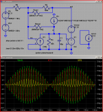
These should tell you a lot if you understand Classical Bode Analysis, the disturbance injection analysis logic – but expecting intellectual resistance I did a transient sim with the B1 nonlinear C model for the “disturbance”
For the transient sim my B1 source is used to model nonlinear C current with the derivative of the voltage, V(x): ddt(V(x)) I then add 2nd and 3rd powers of the derivative in the behavioral source equation
The wave plot shows the relative magnitude of I(C1) and I(B1) – the yellow I(B1) is clearly in phase with red I(C1) trace and plenty distorted
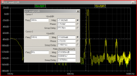
To see the (PIM?) IMD products I simmed with 19+20 kHz 1:1 and looked at the fft plot
By using V(out)@1, V(out)@2 syntax you can look at both feedback conditions, place measurement cursors on each
@1 = no local feedback, @2 = with John’s local feedback Rlfdbk = 500 kOhms
The IMD product at 18 KHz is examined with the cursors – displaying the relative phase, magnitude of this product with and without the local feedback – giving deltas of mdB, ns
There is no meaningful difference, all distortion products are “the same” in the simplified JC-3 power amp sim with or without the local feedback - in amplitude and phase to very high resolution - not at all by the 20-40 dB expected if the local feedback change of node x impedance was significant
If the discussion is centered on the JC-3 power amp schematic: http://www.diyaudio.com/forums/anal...ch-preamplifier-part-ii-1570.html#post2703152
the specific claim is that the inner local feedback loop was added to reduce PIM through the local feedback reduction of the impedance driving the unity gain Darlington output
The idea behind the JC-3 (double feedback loop) was to reduce the OVERALL global feedback to about 20dB, and NOT throw away the initial gain generated by the driver stage, but to use it to linearize the input and driver stage, as well as LOWER the drive impedance to the output stage. Typically the same thing is done with resistor loading of the driver stage, but I hoped for an improvement to this approach. It worked.
This is I believe a claim “testable” in sim – meeting Scott’s criteria
The result is that however John understood it at the time it is easy to show that in a simplified JC-3 sim the local feedback doesn’t reduce at least one simmed source of PIM
I claim a useful but highly simplified model is in the sim below
The input fets, “VAS” Q are modeled as a pure gm
The output is modeled as a Voltage buffer with Av 0.9 to sim speaker loading
The node “x” has estimates of reflected speaker load, Q parasitic R, C
The local feedback Rlfbk is switched in the .step param statement
at the 1st sim “step” parameter a = 0 and the Rfdbk is essentially out of the circuit by being multiplied by 1000x and Rcorr is added in parallel with Ra
at the 2nd ”step” the local feedback active with Rfdbk at the nominal value of ~500kOhm
compensating Rcorr is added in parallel with the outer gain R to correct for the closed loop gain reduction with the local feedback R
I see it as using pretty much the same total loop gain to get the same closed loop result – just “moving” the feedback between inner and outer loops
The added Isource at node “x” is the classic “disturbance injection” of Bode sensitivity analysis – as Putzeys points out it can sim anything about the components connected to node “x” that result in a current change into that node
This could include Q output conductance, driver Q base current, nonlinear C… for AC testing the classic Bode frequency response of the Ierror sensitivity would use the source I put on the side (you have to short, gnd your spare spice cs)
likewise Verror can sim anything that results in a difference between the idealized model and whatever we can write a model equation for taht gives a series V diff - like Vbe, Re V changes with load current
to play with the sim you should look at the classic Bode sensitivities – for the values I guestimated there is virtually no difference in V(out), or V(x) for Ierror AC sweep (move Ierror to the B1 position) despite the swapping in/out of the local feedback - the AC value of all sources except the tested sensitivy should be changed to 0, the active source AC should be 1
in the AC analysis frequency sweep of Vin the input error V(inv) differs by ~1 dB when the local feedback is moved
but looking at Vout, AC sweeping Verror frequency we can see that sensitivity to Verror is reduced ~40 dB when the local feedback isn’t used – just so you don’t miss it these distortions are much lower (~100x) without Rlfdbk
These should tell you a lot if you understand Classical Bode Analysis, the disturbance injection analysis logic – but expecting intellectual resistance I did a transient sim with the B1 nonlinear C model for the “disturbance”
For the transient sim my B1 source is used to model nonlinear C current with the derivative of the voltage, V(x): ddt(V(x)) I then add 2nd and 3rd powers of the derivative in the behavioral source equation
The wave plot shows the relative magnitude of I(C1) and I(B1) – the yellow I(B1) is clearly in phase with red I(C1) trace and plenty distorted
To see the (PIM?) IMD products I simmed with 19+20 kHz 1:1 and looked at the fft plot
By using V(out)@1, V(out)@2 syntax you can look at both feedback conditions, place measurement cursors on each
@1 = no local feedback, @2 = with John’s local feedback Rlfdbk = 500 kOhms
The IMD product at 18 KHz is examined with the cursors – displaying the relative phase, magnitude of this product with and without the local feedback – giving deltas of mdB, ns
There is no meaningful difference, all distortion products are “the same” in the simplified JC-3 power amp sim with or without the local feedback - in amplitude and phase to very high resolution - not at all by the 20-40 dB expected if the local feedback change of node x impedance was significant
Attachments
Last edited:
It all depends on what you mean by "less distortion".simon7000 said:So if I have two stages one with a function of:
Vout = 10,000 x Vin + 50 x Vin ^ 2 + 20 x Vin ^ 3
and the second with:
Vout = 100 x Vin + 50 * Vin ^ 2 + 20 * Vin ^ 3
If I want to get a system gain of 100 is there a combination of local feedback loops that will produce less distortion than cascading both and using global feedback?
However, one thing to try is putting the high gain one in second place, as that has much lower distortion at a given output than the low gain one. Then put local positive feedback around the first (low gain) amp so as to boost the loop gain in the overall negative feedback loop. As this is a gedanken experiment we don't have to worry too much about stability. I can already hear the cries of anguish arising from certain quarters - positive feedback in an audio amp?!
In IC land
Hi Scott
Sorry, I was thinking discrete.
In IC land you have a lot of other things that we lack in the discrete world.
Is it possible to make a discrete transistor (MAT**) with 2 emitters with different Aeff?
That would be nice.
Cheers
S
Hi,
Neither. We where debating the DIFFERENCE between looped feedback for a single stage and degeneration for a single stage when you wrote Post #15777 in which you appears to insist that Nelsons point about lopped feedback and degeneration being different was wrong, cumulating with:
"care to point to a circuit that shows the difference between degeneration, negative feedback that you're asserting?"
If we agree that the two circuits I illustrated are different and behave different than we are on the same page. It makes your challenge quoted above even more strange than if you had actually believed them to be identical.
You constructed a circuit that is not possible in reality to illustrate that if you do that you get certain results. It addresses nothing in the debate but is the same sort of strawman as the "triodes are just pentodes with internal feedback" argument. Really.
Ciao T
I see Thorsten either failed feedback 202 himself or just holds us in such contempt that he feels he can toss up just anything and assert it means he’s right, everyone else is a fool
Neither. We where debating the DIFFERENCE between looped feedback for a single stage and degeneration for a single stage when you wrote Post #15777 in which you appears to insist that Nelsons point about lopped feedback and degeneration being different was wrong, cumulating with:
"care to point to a circuit that shows the difference between degeneration, negative feedback that you're asserting?"
If we agree that the two circuits I illustrated are different and behave different than we are on the same page. It makes your challenge quoted above even more strange than if you had actually believed them to be identical.
Correctly understand the feedback classification system, apply it consistently, and the results really do work, we can show emitter degeneration R gives the same result as “output feedback” in the CE amp at frequencies where the loop gain is large
You constructed a circuit that is not possible in reality to illustrate that if you do that you get certain results. It addresses nothing in the debate but is the same sort of strawman as the "triodes are just pentodes with internal feedback" argument. Really.
Ciao T
Scott,
Actually Scott, I am merely objecting to the fact that you selected a single gain-stage device for your "local feedback makes things worse" example while not pointing out that the results are as a result not universal.
Your results ONLY and STRICTLY applies if the output stage and not the prior stages are the main source of distortion, which is not a given or always the case. One would hope that most designers would apply such logic, but seeing many designs that float around (Commercial and DIY) one sometimes doubts.
I never claimed that the AD844 or LM6181 or AD815 where different except in minor details and (small) performance.
Ciao T
OK folks AM I wasting my time? If we can't agree on what topology means it's going to be rough. HINT: the diode vs follower input devices is a trivial difference (offset considerations). AD844 vs. the LM amp just mentioned.
Actually Scott, I am merely objecting to the fact that you selected a single gain-stage device for your "local feedback makes things worse" example while not pointing out that the results are as a result not universal.
Your results ONLY and STRICTLY applies if the output stage and not the prior stages are the main source of distortion, which is not a given or always the case. One would hope that most designers would apply such logic, but seeing many designs that float around (Commercial and DIY) one sometimes doubts.
I never claimed that the AD844 or LM6181 or AD815 where different except in minor details and (small) performance.
Ciao T
care to point to a circuit that shows the difference between degeneration, negative feedback that you're asserting?
I was waiting for you to ask.
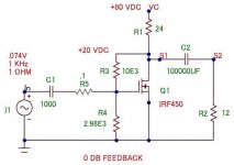
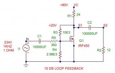
First I have constructed (in MicroCap) an example of a nice little common
Source amplifier without any feedback (except for DC stabilization).
I have done it in a way that a DIYer could build and actually listen to -
obviously I could have made it simpler.
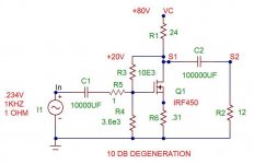
Then I have an example with 10 dB degeneration via a Source resistor.
Then I have an example with 10 dB of loop feedback.
All are driven for a +/- 4 volt output, and the transistor in each case
experiences approximately the same load line.
If you don't think think this is reasonable, let me know.
Attachments
didn't read my page previous post, look at the sim? http://www.diyaudio.com/forums/anal...urls-blowtorch-preamplifier-part-ii-1580.html
you have done the sme thing that Thorsten did - used two diferent classes of feedback, with differing feedback relations and "innocently" offer the suggestion that since both have "10 dB loop gain" they must be equivalent - and since they're not (by your miscontruction) feedback theory must be wrong about degeneration?
anyone willing to actually learn what feedback theory does say? or interested in intellectual honesty in their arguments?
Last edited:
Your results ONLY and STRICTLY applies if the output stage and not the prior stages are the main source of distortion, which is not a given or always the case. One would hope that most designers would apply such logic, but seeing many designs that float around (Commercial and DIY) one sometimes doubts.
Yes but this is so often the case I thought it was of note. Painful as it was remember the Krill, or take note of all the papers by Hawksford, Cordell, etc. The output stage linearity is VERY important in many cases. Most (all?) of the error correction schemes address this. Driving an arbitrary loudspeaker load sometimes requiring amps and voltage and current it goofy phase relationships is what a PA does not a nice 150 Ohm back terminated video line.
PMA the obscure AD8010 is of interest, it was designed to have "no" diffgain/diffphase into 8 video loads in parallel (150/8). The strange bypassing on the datasheet is necessary.
It all depends on what you mean by "less distortion".
However, one thing to try is putting the high gain one in second place, as that has much lower distortion at a given output than the low gain one. Then put local positive feedback around the first (low gain) amp so as to boost the loop gain in the overall negative feedback loop. As this is a gedanken experiment we don't have to worry too much about stability. I can already hear the cries of anguish arising from certain quarters - positive feedback in an audio amp?!
OK Vout can be */- as required. I think you might want to try the math as you suggest it compared to the other way around.
Hi jcx,
You REALLY don't get it, do you. Nelsons argument and mine is that 10dB Gain reduction applied through degeneration and 10dB gain reduction applied through looped feedback are VERY DIFFERENT, while everyone here seems to assert equivalence.
They are commonly referred to as "negative feedback". I prefer to call one "degeneration" and the other "negative feedback". I assume Nelson knows feedback theory, I do as well, certainly it seems we know the difference. Neither Nelson nor myself claim the two types of to be the same, but we claim them to be DIFFERENT.
What DOES feedback Theory say about the Circuits that Nelson and myself illustrated? And no, I am NOT interested in your Sim, because it precisely fails to address the subject.
Ciao T
you have done the sme thing that Thorsten did - used two diferent classes of feedback, with differing feedback relations and "innocently" offer the suggestion that since both have "10 dB loop gain" they must be equivalent - and since they're not (by your miscontruction) feedback theory must be wrong about degeneration?
You REALLY don't get it, do you. Nelsons argument and mine is that 10dB Gain reduction applied through degeneration and 10dB gain reduction applied through looped feedback are VERY DIFFERENT, while everyone here seems to assert equivalence.
They are commonly referred to as "negative feedback". I prefer to call one "degeneration" and the other "negative feedback". I assume Nelson knows feedback theory, I do as well, certainly it seems we know the difference. Neither Nelson nor myself claim the two types of to be the same, but we claim them to be DIFFERENT.
anyone willing to actually learn what feedback theory does say? or interested in intellectual honesty in their arguments?
What DOES feedback Theory say about the Circuits that Nelson and myself illustrated? And no, I am NOT interested in your Sim, because it precisely fails to address the subject.
Ciao T
I was waiting for you to ask.
First I have constructed (in MicroCap) an example of a nice little common
Source amplifier without any feedback (except for DC stabilization).
I have done it in a way that a DIYer could build and actually listen to -
obviously I could have made it simpler.
Then I have an example with 10 dB degeneration via a Source resistor.
Then I have an example with 10 dB of loop feedback.
All are driven for a +/- 4 volt output, and the transistor in each case
experiences approximately the same load line.
If you don't think think this is reasonable, let me know.
Since you have done them in MicroCap, no doubt you would also show us the distortion spectra ??
Thanks,
Patrick
PMA the obscure AD8010 is of interest,
I only have a datasheet of this part.
Hi,
For small signals into audio it is trivial to make output stages with very low THD, low enough that noise is more relevant (see Samuel Groners DI Box for example SG-Acoustics · Samuel Groner · Miscellaneous). In most power amplifiers it equally trivial to make an output stage that has open loop sub 0.5% THD at full power below, if we use "local loop" output stages even 0.1% are achievable. The reason of course is that output stages operate at essentionally 100% negative feedback.
Class B operation makes things more difficult, however, in MOST Audio Amplifier and Preamplifier circuits the main source of distortion is NOT the output stage, but the VAS Stage. There exceptions, namely circuits with well above average linearity in the earlier stages but poor output stage linearity, outside IC's where the current and dissipation budget of output stages is cramped by economy and forces compromises they are rare.
Yes, however many methods exist to achieve good linearity with output stages.
Ciao T
Yes but this is so often the case I thought it was of note.
For small signals into audio it is trivial to make output stages with very low THD, low enough that noise is more relevant (see Samuel Groners DI Box for example SG-Acoustics · Samuel Groner · Miscellaneous). In most power amplifiers it equally trivial to make an output stage that has open loop sub 0.5% THD at full power below, if we use "local loop" output stages even 0.1% are achievable. The reason of course is that output stages operate at essentionally 100% negative feedback.
Class B operation makes things more difficult, however, in MOST Audio Amplifier and Preamplifier circuits the main source of distortion is NOT the output stage, but the VAS Stage. There exceptions, namely circuits with well above average linearity in the earlier stages but poor output stage linearity, outside IC's where the current and dissipation budget of output stages is cramped by economy and forces compromises they are rare.
Painful as it was remember the Krill, or take note of all the papers by Hawksford, Cordell, etc. The output stage linearity is VERY important in many cases. Most (all?) of the error correction schemes address this.
Yes, however many methods exist to achieve good linearity with output stages.
Ciao T
Since you have done them in MicroCap, no doubt you would also show us the distortion spectra ??
Since JCX has disposed of my examples as not representing loop feedback
vs degeneration, I don't see the point.
But of course I will anyway.
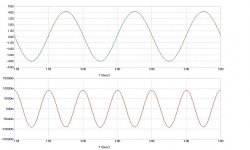
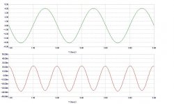
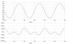
I am only going to show you the distortion waveforms created by subtracting
the scaled input from the output.
The first is no feedback, the second is degenerated, and the third is loop.
I am only going to show you the distortion waveforms created by subtracting
the scaled input from the output.
The first is no feedback, the second is degenerated, and the third is loop.
Attachments
Hi,
Class B operation makes things more difficult, however, in MOST Audio Amplifier and Preamplifier circuits the main source of distortion is NOT the output stage, but the VAS Stage. Ciao T
Not addressed by that connection either, a story for another day. I disagree BTW except of course in valve amps. One would think the endless wining about crossover distortion had some basis. After all Dr. H and Bob both showed that eliminating it improved (sometimes dramatically) the performance. OTOH isn't it you that has little or no interest in distortion? FET inputs and good VAS's have a hard time making anything over the third harmonic.
The "typical" audio amp has load independent distortion??
Last edited:
- Status
- Not open for further replies.
- Home
- Member Areas
- The Lounge
- John Curl's Blowtorch preamplifier part II