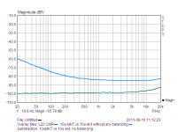
10u MKTcap vs. 10u elyt, without any balancig. Lower graph is my measurement limit. Same results with noise or swept sine. Many amps will be 20dB worse (in/out comparation)..I don't think that a simple difference test will tell us much, either.
Just look at the results of a SINGLE capacitor, compared to a higher quality capacitor, such as a 1uF Teflon in the test that Walt Jung and I did, back in 1985 or so.
A single Mylar cap could give you a -70dB residual, even with compensation for inductance, resistive ESR, and value differences. How can a complete power amp, especially with input coupling caps do any better?
Attachments
I don't think that a simple difference test will tell us much, either.
Just look at the results of a SINGLE capacitor, compared to a higher quality capacitor, such as a 1uF Teflon in the test that Walt Jung and I did, back in 1985 or so.
A single Mylar cap could give you a -70dB residual, even with compensation for inductance, resistive ESR, and value differences. How can a complete power amp, especially with input coupling caps do any better?
Then again john, I could point you real world at have <1ppm total THD at full power, and still vanishingly low at lower levels. Sure they use a lot of feedback, but you need to use the right parts - and we know elco's and mylars have issues in audio, as do cheap ceramics. I am simply reminding you here of what you have been telling everyone on this thread for the last few years BTW
10u MKTcap vs. 10u elyt, without any balancig. Lower graph is my measurement limit. Same results with noise or swept sine. Many amps will be 20dB worse (in/out comparation)..
BV, can you share the test set up with us? You show -100dB on the good quality cap, but I would expect something much lower than that. Are your results limited by the source oscillator? I am also surpised by you elco result given the kind on numbers Doug Self shows in his book 'Small Signal audio Design'
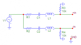
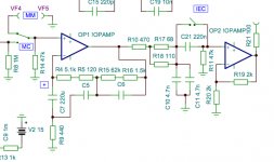
Bonsai, used set up is in attached picture . The same signal (swep sine, noise, music..) in two capacitors under comparison, conected to balanced input (+In, -In ,GND) of quality soundcard (Lynx L22, R3, R4 is input impedance of soundcard)). Lover trace in picture in my previous post is CMRR limit of my soundcard (the same signal with 0dBV conected to both +In , -In inputs, shorted together), upper show unbalance influence caused by different transfer in both signal paths.
Attachments
Last edited:
I can not personally verify the text below, but it is rather interesting, regarding limitations of digital sound
""Mathematician Jean Baptiste Joseph Fourier invented simple way of representing the diverse nature of the batch process through the expression of the process as a sum of sines and cosines of multiple frequencies. Only for periodic processes. Not for any other. One should be aware that the process is 100% periodic. Later mathematicians managed to stick this way for non-periodic processes, more precisely, for pieces of non-periodic processes. The sum of sines and cosines necessarily becomes infinite and therefore has a way only of theoretical significance.
What did from this electronics engineers? Correctly, they just started using it everywhere.
The funny thing is that none of them asked each other: guys, maybe we do with your non-periodic signal? For mathematicians there would be no doubt: once the baseline method are not met - method does not apply. Radio technicians, with their "accelerated courses" of higher mathematics that did not stop. Thus was born the famous "theorem" of readings in 1933 comrade Vladimir Aleksandrovich Kotelnikov. He was then 25 years, he lived in Kazan, his dad was a teacher of higher mathematics at the University, and, apparently, no pope has not done it because "theorem" report implicitly offered much earlier in the form of a numerical method to interpolate functions given in tabular form.
The first mistake was
that the "theorem", "range" of the signal was understood as the result of processing of the signal Fourier transform. That is understood that sampled and restored signals - periodic and bounded in amplitude. Therefore the proof of "Theorem" has been reduced to a tautology: the condition of the limited range of signal (Fourier) representation of the signal above is equivalent to a countable number of sinusoids of multiple frequencies. That is was: a periodic signal, which can be represented by Fourier series as a finite sum of multiple frequencies, we can recover the points by interpolating the finite Fourier sum. Radioengineering interpret it this way: any signal, which succeeded with the help of passive filter to suppress the higher frequencies well, you can just restore the individual (not very accurate) readings with the same linear passive low pass filtering.
The second mistake was
that Kotel'nikov drew a graph of the spectrum to restore the signal not correctly. The fallacy of the graph of the signal by Kotelnikov is that the spectrum is limited to the left by zero. That is, consists of an infinite number of spectral components of low frequency. But this can not be due to the fact that the signal is then not limited in amplitude, that is not the conditions of the limited amplitude of the signal, as well as the convergence of the Fourier integral at infinity - a necessary condition for the existence of the Fourier spectrum. Signal, even periodic, - for the restoration of Kotelnikov should be limited in range and below. And no worse than the top. You know what's funny? The thing is that almost all modern mixing consoles for digital audio include very steep high frequencies filters, which greatly weaken the signal frequency components. Not only that, the latest models also contain a studio microphones with high pass filter.
The third mistake,
"theorem" of readings is that it "proved" to signal to the spectrum of a rectangular shape. At the same time restoring (interpolating digital readout point) has the form sin (x) / x. In the "theorem" says nothing about what should be restoring function for a signal with non- rectangular spectrum. And it must have a very different kind. I personally find ridiculous, that it was much later Kotelnikov his "theorem" counts laid the foundations of the theory of optimal filtering, which asserts that for signals with different spectra of the different needs different restoring function (read - different filters). That is, a change of the signal leads to change of the output filter and digital to analog converter!
Mates! You over there in Moscow, go to the Academician Vladimir Aleksandrovich Kotelnikov - he is now 91, he is still alive and edits the magazine "Radio" - and ask him what he thinks about the inadequacy of digital sound.
Americans are even now take very serious about sampling theorem, which now is in the basis of all communication theory and analysis of radio circuits. They do not even whisper about it wrong! America's "theorem" Shannon sampling invented in 1949. One to one, as by Kotelnikov!
Where the exit from a digital dead end? Ask Sony!
Stop, you can not ask - president of Sony, said the editor of the Journal of Mass audiophile in the world "Stereophile", that Sony does not see the need for a new digital audio format.
How many giga-baks cut down Sony from digital audio? A lot. Megabucks how Sony has spent only on advertising promotion silly (the sound) mini-disk? About three hundred million dollars according to official data very Sony. How much she spent on serious scientific research in the field of sound? Zero? Slightly greater than zero.
Sony bought the entire archive of good analog record company RCA, and it's going to do with it? That's right, to digitize "for better persistence." "
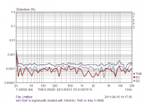
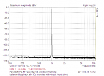
Bonsai, if You are talking about capacitor THD, posted graphs have nothing to do with THD. It is in attached pictures (THD vs . freq. limited by soundcard resolution at fs 192kHz).You show -100dB on the good quality cap, but I would expect something much lower than that. Are your results limited by the source oscillator?
Attachments
I don't know where Vladimir found that text, but it is difficult to comment on something which is so badly translated that it is unclear what it is actually claiming. It seems to mix up Fourier and Shannon, although these are obviosuly related.
First alleged mistake: that Fourier theory is essentially tautologous. No, Fourier theory states which functions it can be applied to. IIRC Fourier analysis can be applied to any periodic function with a finite number of finite discontinuities. Fourier transform extends this to non-periodic functions. For people worried by this there is always wavelet transforms instead.
Second alleged mistake: I simply don't understand what is being said. A better translation into technical English is needed here.
Third alleged mistake: the theory only applies to signals with a rectangular spectrum. Not true, it merely requires that no components exist above a particular frequency. If such components do exist, then you get aliasing. Nothing new here, merely misunderstanding. Sin(x)/x (i.e. sinc) is mentioned. You get a sinc frequency response from a sample-and-hold DAC output (first-order hold?). The solution is to use a zero-order hold (e.g. Dirac delta spikes before the reconstrucntion filter). Not a fundamental problem, just an engineering complication.
I'm not sure why it is felt necessary to occasionally lob into the discussion a 'grenade' from Russian science which allegedly undermines current (Western?) audio engineering. So far, the grenades haven't gone 'BANG' but just 'poof'. The nice thing about maths is that Russian maths has to be the same as maths everywhere else, so correct maths correctly applied is valid everywhere. The theoretical underpinnings of audio engineering are quite safe, although often misunderstood by people who don't get maths.
Second alleged mistake: I simply don't understand what is being said. A better translation into technical English is needed here.
DF96, I believe that you are write, but, at the same time, observing how "well grounded" official hi-fi standards, I start to doubt in everything.
The second "mistake" is that the spectrum considred must be limited not only by maximum frequency, but also by a minimum frequency, it must not go up to zero at the bottom end. An author states, that it is not so by both Kotelnikov and Shannon.
we don't give the performance venue local atmospheric pressure reading along with the recording - Musical Sound transmission in air is Zero Mean
the pattern of citing unavailable "references" and asserting "problems" with basic math assumptions to "discredit" engineering practice is a bit foolish with such mature, widespread, proven effective technologies - you are certianly getting closer to being filed under "Troll" in my estimation
undergrad EE textbooks can be somewhat lose with the math since the emphasis is getting usable tools in the hands of working engineers but justifications for single sided transforms are solid despite the "ad hoc" patches to the simpler theory that is so much easier to learn, apply
Last edited:
We have found that even a single Mylar cap cannot be nulled to beyond -60dB, using a bandwidth limited asymmetrical pulse with a 20ms (for example) length, and a bit of time left for settling. You cannot use a sine wave sweep of any kind to see this, but MUSIC will have enough dynamic asymmetry to show it.
I have measured about 5% or -45dB with a typical aluminum electrolytic capacitor with the same test, hundreds of times. Anyone can duplicate Walt's, Scott's and my efforts by re-running our test. Just go to Walt's website and get the paper. Remember everyone, this is for a SINGLE capacitor, compensated for inductance, resistive ESR and measured value. This is a measurement of one RC vs another RC, yet we cannot get a good null without an EXOTIC cap.
I have measured about 5% or -45dB with a typical aluminum electrolytic capacitor with the same test, hundreds of times. Anyone can duplicate Walt's, Scott's and my efforts by re-running our test. Just go to Walt's website and get the paper. Remember everyone, this is for a SINGLE capacitor, compensated for inductance, resistive ESR and measured value. This is a measurement of one RC vs another RC, yet we cannot get a good null without an EXOTIC cap.
Last edited:
We have found that even a single Mylar cap cannot be nulled to beyond -60dB, using a bandwidth limited asymmetrical pulse with a 20ms (for example) length, and a bit of time left for settling. You cannot use a sine wave sweep of any kind to see this, but MUSIC will have enough dynamic asymmetry to show it.
I have measured about 5% or -45dB with a typical aluminum electrolytic capacitor with the same test, hundreds of times. Anyone can duplicate Walt's, Scott's and my efforts by re-running our test. Just go to Walt's website and get the paper. Remember everyone, this is for a SINGLE capacitor, compensated for inductance, resistive ESR and measured value. This is a measurement of one RC vs another RC, yet we cannot get a good null without an EXOTIC cap.
I think that the question here is not whether the capacitors introduce distortions but rather if the distortions remain even after being corrected by a (big) negative feed-back ?
Hi,
There are often capacitors present in amplifiers that are NOT "being corrected by a (big) negative feed-back".
Ciao T
I think that the question here is not whether the capacitors introduce distortions but rather if the distortions remain even after being corrected by a (big) negative feed-back ?
There are often capacitors present in amplifiers that are NOT "being corrected by a (big) negative feed-back".
Ciao T
Hi,
There are often capacitors present in amplifiers that are NOT "being corrected by a (big) negative feed-back".
Ciao T
Can you elaborate ? Apart from the input one which sees a small signal I can only think of the output capacitor for those amps that have them. Many of the high end ones connect directly to the speakers (may be different for the tube amps).
Mr. Curl, measurements I posted, are for sole capacitor in series with signal (sweep sine, noise, music, asymetric pulse,etc.., results are the same). No active components,so no feedback. Capacitor was conected as coupling capacitor (NOT AS OUTPUT CAPACITOR IN POWER AMP!!!), with reasonable load, so AC voltage across capacitor in whole audio range is negligible. So it is the same then for added distortion (no AC, no distortion), it is negligible. Try to repeate measurements, simply put capacitor in series with signal in loopback in AP system ...Exposing capacitor to whole AC (conected in series with relatively small resistor as "load" at generator output) tels nothing about distortion in "normal" use.
If you did what you stated, then you either had a very good cap, or the cap was not 'working' within the bandwidth that you measured, or the test was too 'easy'. This can be shown with Walt's and my paper where I tested a 10uF aluminum cap against an 8uF Rel. polypropylene with a nominal 50K load. I got, (best case) 0.19% or about -54dB. This is with just ONE CAP! And by canceling any ideal or static characteristics of the cap on test.
I SPECIFICALLY referred to input caps. However, output caps or feedback caps also fit in the equation. Feedback caps, the ones that block DC and create more feedback at low frequencies, do NOT have any feedback around them.
Thanks for the mentioning the caps in the feed-back circuit: usually I think of it just as a resistive divider, like for the op. amps.
Here is a little trick that rescues at least the treble in an inexpensive MM phonostage i made. C5 that can be a film and foil PP bypasses C7. That created a small error at 20HZ ( ca. 0.5dB ) that can be cancelled to better then 0.1dB with a 15 Ohm resistor in series with the 220uF elcap.
Attachments
- Status
- Not open for further replies.
- Home
- Member Areas
- The Lounge
- John Curl's Blowtorch preamplifier part II