It does NOT improve by just making the OL BW higher.
Yes Jan, it does not. I made a nice experiment with preamp with the same GBW and modified only OLG corner by VAS load. Current through Cc remains the same, the only difference is much higher distortion, as the VAS and input stage are forced to work more hard.
Regards.
You mean "We turn all our obsolete technologies into art." ?
You're makin' fun of my tubes, aren't you?

Yet... no PIM, SID, TIM, FIM, or LSMFT.
experiment
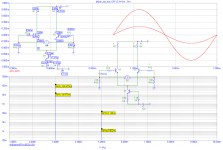
I have to mention the topology. It is similar to that from Gilbert's paper, BUT with JFET input differential stage. The input bipolar LTP is the source of most troubles we discuss here. And emitter degeneration is no cure, as voltage noise increases rapidly and grossly then.
It appears that when you modulate the open loop gain with normal [AM] distortion, you move the effective bandwidth back and forth, creating FM or PM distortion, due to the difference between the working bandwidth and the open loop bandwidth, and the 90 degree phase shift necessarily due to the compensation capacitor. This creates a distortion term that is 90 degrees out of phase with the input signal, and the vectorial summation of the sine (initial waveform) and the cosine (distortion waveform caused by the 90 degree slope) add vectorially and cause a dynamic phase rotation that is directly related to the square of the input signal, and [signal frequency/gain bandwidth]squared.
Got it. This refers to the dynamic case where the open loop bandwidth is changing with signal.
I was thinking of the (perhaps) simpler case where the applied signal is already angle modulated (FM or PM). Then, having a non-flat gain curve in the band where these signals reside will cause FM/PM to AM conversion. This would certainly be the case if there was no feedback applied. I can't even guess how many 100's of millions if not billions of FM radios have been built on this principle for demodulation over the past 3/4 of a century.
I should have been more clear - my bad.
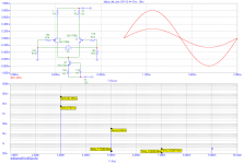
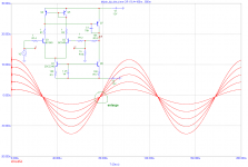
Let's make the same with JFET input LTP. To get same output current amplitudes, we have to increase input differential voltage to 12mV and 36mV. Anyway, we get considerably lower distortion than with bipolar LTP, for same idle current. And we can allow much higher input differential voltage now.
Attachments
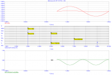
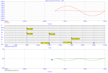
We are also interested in Gm variations with amplitude - this is the key factor. Next two images add normalized Gm (green) for both FET and bipolar simulations. Again, we can see that Gm variations for FET input stage are lower than those for bipolar LTP, for the same idle current and same output signal current.
Attachments
Except for the COS term that will suddenly appear.
Nope you ARE wrong. You have misread, misinterpreted, or misunderstood what Barrie wrote. Please follow PMA’s examples. Barrie wrote that article in a moment of trying to get people interested in some of his open loop current transfer circuits, mainly for DC to GHz applications where op-amp performance gets weak
Last edited:
Barrie Gilbert's article supports the 'fact' that a low open loop bandwidth allows 'conversion' of AM to FM, at least that is how I read it. I also agree that higher gain bandwidth is better, all else be equal, and a more linear input stage is better, all else be equal. Anything else?
John,
You are reading it wrong, or at least reading stuff into it that is not there. Barrie is smart and correct, but insofar as PIM goes, he is Johnny-come-lately and does not address all of the issues.
My paper, here, is the one that should be read:
http://www.cordellaudio.com/papers/phase_intermodulation_distortion.pdf
It was done 30 years ago and covers all the bases Barrie did, and more.
Cheers,
Bob
We are also interested in Gm variations with amplitude - this is the key factor. Next two images add normalized Gm (green) for both FET and bipolar simulations. Again, we can see that Gm variations for FET input stage are lower than those for bipolar LTP, for the same idle current and same output signal current.
Good stuff Pavel!
jan
PIM
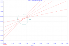
Now, this is the PIM
In case we explore the LTP without feedback, all the lines intersect in the same point. Feedback converts the Gm variations (in amplitude) to PIM (in time, phase).
BUT, I have to say B as well. This is seen only in a difference of LTP currents, NOT in the output voltage.
Now, this is the PIM
In case we explore the LTP without feedback, all the lines intersect in the same point. Feedback converts the Gm variations (in amplitude) to PIM (in time, phase).
BUT, I have to say B as well. This is seen only in a difference of LTP currents, NOT in the output voltage.
Attachments
Last edited:
Pavel,
you show plots using bipolar input stages, undegnerated, with high differential input voltages.
In an op-amp with global -ve feedback you are not going to see these large differential voltages on a sine wave input, unless you are above the 3dB corner frequncy - i.e. where there is no longer any feedback.
On bi-polar discrete circuit with much lower loop gains, I agree you will see this problem . . . but then experienced designers would not build an undegenerated discrete circuit like the one you are showing unless the input signal was very small.
Am I missing something here?
Last edited:
Bonsai, I think you are missing something. First I showed plots for bipolar differential input, voltage 3mV and 9mV at 10kHz. In case you have an opamp with 10MHz GBW and dominant pole -6dB/oct compensation, it will have OL gain 1000x (60dB) at 10kHz. If you have 5V/10kHz at the output of the closed loop circuit, you need 5mV at the input. This is just covered by the 1st plot I have shown here:
http://www.diyaudio.com/forums/anal...ch-preamplifier-part-ii-1265.html#post2592233
, and you can see that the LTP distortion is quite high. If you change input differential voltage from 0mV to 5mV, you will get quite large change in input LTP distortion and Gm.
http://www.diyaudio.com/forums/anal...ch-preamplifier-part-ii-1265.html#post2592233
, and you can see that the LTP distortion is quite high. If you change input differential voltage from 0mV to 5mV, you will get quite large change in input LTP distortion and Gm.
Last edited:
For example, open loop vacuum tube amps would NOT have this distortion. Solid state CAN have some, even operating open loop, BUT it should just get worse with yet another phase shifting mechanism added.
Once again, I am only the messenger.
Wrong again, John.
Vaccuum tube amplifiers DO have PIM mechanisms in the open loop. Perhaps the biggest one is output transformer core saturation onset, which can modulate the phase delay through the transformer at levels beginning well below core saturation.
You are also wrong about the open-loop and feedback PIM mechanisms being additive. Read my paper. Negative feedback reduces the PIM that is generated by the open-loop PIM mechanism.
Some of these things can be non-intuitive, and I think that is where you are being led astray.
Cheers,
Bob
Now consider you have the same circuit, but with JFET input stage. You will again need 5mV input at 10kHz, but then you are far below the lowest curve here
http://www.diyaudio.com/forums/anal...ch-preamplifier-part-ii-1265.html#post2592251
which is for 12mV input. So you get even higher reduction of input stage distortion and Gm variations than I have shown for the same Ic currents of BJT and JFET.
http://www.diyaudio.com/forums/anal...ch-preamplifier-part-ii-1265.html#post2592251
which is for 12mV input. So you get even higher reduction of input stage distortion and Gm variations than I have shown for the same Ic currents of BJT and JFET.
Now, this is the PIM
A picture is worth a thousand words.
How does that circuit do when you use a resistive load
off the diff pair?
PMA, REALITY is where people use what op amps are cheap and available. The 5532 comes to mind and 4558. Give me a break, that is WHAT MAJOR MANUFACTURER'S USE.
Both in pro audio and mid fi consumer level. Let's say you want to buy an SACD player, what will you get, GENERALLY?
I personally have been designing with the best 'practical' IC op amps that I can find, and I find each and every one slightly different, sonically, and it's hard to get enough 'sonic quality' to compete with discrete designs. Distortion measurements can be remarkable, however, but THAT is not enough, for true sonic enjoyment. Why, is the question.
John, I thought we were discussing high end here. Like Blowtorch and other good discrete circuits. Or the best opamps.
My Marantz SACD has completely discrete analog board, with not a single opamp used.
You give me a break with 4558, 741 and 40 years old stories of 0.5V/us opamps. Please do not forget to mention the uA709 , also a 'great' opamp to tell story about. You live in the past, and that is your big problem.
- Status
- Not open for further replies.
- Home
- Member Areas
- The Lounge
- John Curl's Blowtorch preamplifier part II