Yes but only if the amp itself has sufficient OL gain at that point, right? Suppose the amp has 30dB OL gain at 20kHz, you can put in all the nfb you want but for full power (80V pk-pk) you do need 80/30dB ~ 2.7V differential input signal at the LTP. I don't see that you can get around that.
So, are you saying that a good power amp has 80dB or more OL gain at 20kHz?
jan
Jan, I would think that, in a power amp, the input pair on a bip LTP would be heavily degenerated and that would take care of the issue for reasons similar to the use of JFET LTP. Of course it's a different story on a small signal amplifier.
But heavy degeneration of input bipolar LTP increases equivalent input voltage noise. We do not want it. 2SK170BL input pair would have lower voltage noise than bipolar with emitter degeneration. Not speaking about input current noise of the bipolar that is VERY unwanted.
Why not to consider multitanh bipolar cell rather than degenerated bipolar LTP.
Why not to consider multitanh bipolar cell rather than degenerated bipolar LTP.
we are talking Audio, not Ocilloscopes
I don't see where low single digit microsecond settling times have been shown to be relevant to audio - yet another engineering measurement that correlates poorly with "good sound"?
on signal content alone it is extremely implausable that microsecond amplifier settling time (2 uS to 0.1% in my example circuit) is important to commercial recorded music signals that have been 4th order low pass filtered at 50 KHz or less (usually much less) by the combination of recording microphones and loudspeaker transducer's basic physics limits even without consideration of electronic processing or recording/playback limitations (phonograph records put 2 more 2nd order mechanical low pass transduction steps in the signal chain with cutting head and stylus/cantilever resonances)
then there is the data from actual psychoacoustic testing where Temporal Masking is well established and strong for forward masking with time constants in milliseconds - most temporal masking models are even single pole as well as using 10's millisecond time constants
ie 100's x longer than even the -120 dB settling time of my composit amplifier example circuit
Last edited:
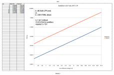
It is just THD, not THD+N. For noise analysis, please consider the part used. With 2SK170BL, you can get about 0.8nV - 1nV/rt(Hz) of equivalent input voltage noise. In a real life application, you may be somwhere at 2nV/rt(Hz). This is very hard to obtain with degenerated bipolar input. The aim is to show that input JFET LTP is much more linear and that it can accept higher input differential voltage. This is of course well known, but maybe some people sometimes do not realize the real numbers.
But heavy degeneration of input bipolar LTP increases equivalent input voltage noise. We do not want it. 2SK170BL input pair would have lower voltage noise than bipolar with emitter degeneration. Not speaking about input current noise of the bipolar that is VERY unwanted.
Why not to consider multitanh bipolar cell rather than degenerated bipolar LTP.
Hi PMA,
As you know, I prefer JFET input pairs on power amplifiers. However, when BJT input pairs are used, I do degenerate them by a factor of 10, which you would probably describe as heavy degeneration. It is certainly true that degeneration adds voltage noise to the input stage. However, for a power amplifier, 5 nV/rt Hz input noise is considered very good. This is not difficult to achieve with a heavily degenerated BJT input pair.
BTW, speaking of multitanh BJT cells, I describe a JFET cascomp in my book Designing Audio Power Amplifiers in Figure 25.13 on page 522. Although the JFET does not follow the BJT tanh behavior, the cascomp principle applies equally well. It reduces distortion by a factor of 6:1 at high signal levels as compared to a conventional JFET LTP. I have not seen the JFET cascomp described anywhere previously, and would be interested in any available references to it that you might be aware of.
Cheers,
Bob
Cheers,
Bob
OK, but still. Even with an 80mV linear input range you'd need 60dB OL gain at 20kHz to avoid gross non-linearity and thus PIM. Is that realistic? Or are we chasing a ghost? If we exceed the linear range by some amount, how much PIM is actually generated, does anyone have any numbers for that? Walt? Bob?
jan
Hi Jan,
The key to understanding feedback-generated PIM is to recognize that the normal amplitude intermodulation distortion (AIM) of an input stage corresponds to an incremental gain change as a function of instantaneous signal level. That gain change modulates the open-loop gain and thus the feedback gain crossover frequency. That in turn corresponds to a modulation of the closed-loop frequency pole frequency, which in turn creates a variation of phase (due to that pole) in the audio band.
Thus, it is the variation of the closed loop pole that is important. The further out the closed loop pole (higher closed loop bandwidth) the less the amount of phase lag from that pole in the audio band to be modulated.
This is why it is the closed loop bandwidth that counts, not the open-loop bandwidth.
For this mechanism, it is virtually impossible to have PIM without having substantial AIM (which in turn corresponds to substantial THD-20 and 19+20kHz CCIF). Indeed, feedback-generated PIM is just a partial amplitude-to-phase conversion of AIM. Bottom line: if HF harmonic and intermodulation distortion is very low, feedback-generated PIM will be very low.
I suspect that one might be able to create PIM without AIM if one tried using a nonlinear all-pass function, but one would still see the results of PIM in a high-frequency distortion test like 19+20kHz CCIF as distortion sidebands.
Cheers,
Bob
What's a floating input cap?Blowtorch goes through: ... floating input cap...
apples and oranges ???
Without knowing the gm of the BJT respectively JFET LTP stage, your figures are not really convincing, at least to me.
Also, what about a comparison of the two LTPs, based on equal output current, instead of equal input voltage?
Hereby the summary - comparison of THD in bipolar and JFET LTP, for input differential voltage from 1mV to 50mV. Above 57mV, the bipolar LTP starts to clip.
Without knowing the gm of the BJT respectively JFET LTP stage, your figures are not really convincing, at least to me.
Also, what about a comparison of the two LTPs, based on equal output current, instead of equal input voltage?
based on equal output current, instead of equal input voltage?
If you kindly read older posts, you would find comparison with equal output currents
And you can see parts used and idle current.
And the Gm could be read even in the older images.
Last but not least, it is the input voltage that counts. Output voltage divided by LG at frequency of interest defines input differential voltage of the feedback circuit.
Last edited:
But heavy degeneration of input bipolar LTP increases equivalent input voltage noise. We do not want it. 2SK170BL input pair would have lower voltage noise than bipolar with emitter degeneration. Not speaking about input current noise of the bipolar that is VERY unwanted.
Why not to consider multitanh bipolar cell rather than degenerated bipolar LTP.
PMA, I agree the degenerated bipolar is noiser. Tanh pair I need to try - I have not used that technique.
Having said that, I do have 2 off LSK389's that I got as samples waiting to be used in a project . . .
If you kindly continued reading, you would find comparison with equal input voltages
I asked: what about comparison with equal output currents.
And you can see parts used and idle current.
And the Gm could be read even in the older images.
http://www.diyaudio.com/forums/anal...ch-preamplifier-part-ii-1269.html#post2593346
So we are supposed to waste our time by digging into older pages?

Alway the same trouble with you: missing (or scattered) info.
I describe a JFET cascomp in my book Designing Audio Power Amplifiers in Figure 25.13 on page 522. Although the JFET does not follow the BJT tanh behavior, the cascomp principle applies equally well. It reduces distortion by a factor of 6:1 at high signal levels as compared to a conventional JFET LTP. I have not seen the JFET cascomp described anywhere previously, and would be interested in any available references to it that you might be aware of.
Bob,
You may want to check "Wideband Amplifier Design" - Allen L. Hollister - Scitech Publishing Inc. pag.265, Figure 4-33.
Best Regards
Giorgio
.........
Last but not least, it is the input voltage that counts. Output voltage divided by LG at frequency of interest defines input differential voltage of the feedback circuit.
Of course, the gain (gm) is totally irrelevant.Just for the record, distortion of 2SK170BL pair is about 3 times lower than that of BC549 pair, with regard to same output current. Both pairs with tail current 5.8mA.
21mS vs. 88mS
Thank you so much! What about the distortion of the BJT pair with degen. resistors such that gm is also 21mS (i.e. equal to the JFET pair)?
Well, I'm still waiting for an answer. Or don't you like to publish the outcome?
In meantime, I figured it out by myself. For equal gm I've set the degen. resistors at 34.6 Ohms. Now the distortion of the BJT stage (with Vi=50mVpk) is 37% lower compared to the JFET stage.
edit: PS: I've simmed this with MicroCap V9 models.
In meantime, I figured it out by myself. For equal gm I've set the degen. resistors at 34.6 Ohms. Now the distortion of the BJT stage (with Vi=50mVpk) is 37% lower compared to the JFET stage.
edit: PS: I've simmed this with MicroCap V9 models.
Last edited:
- Status
- Not open for further replies.
- Home
- Member Areas
- The Lounge
- John Curl's Blowtorch preamplifier part II