I don't see why a DAC would clip at full scale digital input, with the exception of lousy design.
There appear to be a few of those around. Confusing is that there are 2 definitions of 0dBFS as well, which are 3dB apart.
I did have a reference as to why the clipping occured but have lost it and brain not working

Edit: Jan I believe there are 2 problems. One is some DACs clip at 0dBFS, and then 'overs' in the reconstruction. But I may be badly wrong again!
Isn't the issue that the reconstruction filter can come up with an analog value higher than expected with 0dB full scale, and then clipping on the analog side?
Jan
If you connect samples by just drawing straight lines between them, you don't get anything over full scale. But that's linear interpolation and it causes intermodulation with the samplerate.
The next step up is cubic interpolation or others which draws a curve between samples, which is much better but still just an approximation. The curve that's drawn can go over full scale.
FFT-based resamplers can be relatively exact but that is only ever done in software. But, they could still have the same problem.
It only makes sense when you look at those ripply square waves, it has to be going over full scale to make those ripples if the square wave is at full scale.
Last edited:
FFT-based resamplers can be relatively exact but that is only ever done in software. But, they could still have the same problem.
It only makes sense when you look at those ripply square waves, it has to be going over full scale to make those ripples if the square wave is at full scale.
You can carry sinc reconstruction out to as many digits as you want, there is a maximum increase in crest factor due solely to this process but I think 3dB is too much. I think some folks are rolling other factors into the process.
I hear LHC has moved beyond Higg's boson this is really a great time for science.
gravitational asymmetry?
The Higgs FAQ 2.0 | Of Particular Significance
THx RNMarsh
Sheesh. Rename aether to higgs, suddenly they care...
John
I don't see why a DAC would clip at full scale digital input, with the exception of lousy design.
Am I right that the gain structure problem is when nonlinear interpolation comes up with a value higher than full scale output? And that to avoid this, I need to set my digital source to -3db (or some other fundamentals-derived number)?
This explanation is given here:
Audio That Goes to 11 - Benchmark Media Systems, Inc.
“Digital systems take a snapshot of the audio signal thousands of times per second. These snapshots or "samples" represent the audio signal at an instant in time. In between successive samples, the audio is always changing. Digital sampling systems often miss short audio peaks which occur between these samples. These peaks often "go to 11", but are entirely missed by the sampling system.
Nevertheless, the short peaks between samples are not lost! These peaks that "go to 11" can be reconstructed from the surrounding digital samples. The DAC (digital to analog converter) in an audio system is equipped with digital reconstruction filters that can recover these inter-sample peaks. These filters work wonderfully until the digital processing overflows. Peaks that hit "9" or "10" will not cause an overflow, but peaks that "go to 11" may cause an overflow.”
Actually, I'm using a software resampler to resample everything to 192KHz, so my DAC doesn't badly interpolate anything (that's the theory anyways). So, should I set the resampler input to -3db?
Also what is the real likelihood that interpolation will produce such high peaks when playing music? Doesn't the frequency have to be near Fs/2 as well as being near full scale?
I find the 3dB in any case as an unlikely possible high excursion above 0dB.
It’s good to do THD measurement using sinusoid input for to be more specific.
A sinusoidal 11025Hz signal is shown to be used as a test, see Fig.2 here (I don’t know what they mean by ‘45 Degrees’)
Benchmark DAC2 vs. DAC1 - Is There an Audible Difference? - Benchmark Media Systems, Inc.
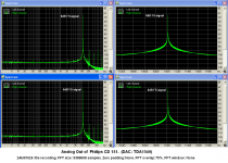
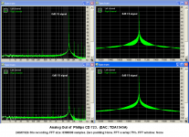
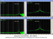
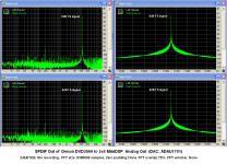
So I had software to generate the 11025Hz sinusoid signal at various levels and recorded some 44100Hz 32bit float files. (at 0dB FS, -0.1dB, -0.2dB, -0.3dB, -0.4dB, -0.5dB, -1dB, -1.5dB, -2dB, -2.5dB, -3dB, -3.5dB, -4dB, -4.5dB, -5dB, -5.5dB, -6dB).
I dithered and saved them as 44100/16bit 30s duration each.
I burned a CD and played it on three CD players. I recorded the signal coming from the Analog Out .
I also fed the digital input of the 2x4MiniDSP (ADAU ) through a PC USB out and through the SPDIF out of a CD player. I played the files and recorded the analog out of the MiniDSP.
Recordings were done in 16/44.1k, 24/96k, 24/192k through a M-Audio Audiophile USB external sound card (a 3db attenuator was used to record the analog out of the CD players and DVD player for not to overload the input of the card)
In all cases, the 0dB FS signal was handled very well.
All DACs performed to their 0dB FS specification.
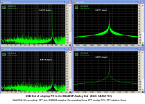
I attach the FFTs from the 24/192k files at 0dB and –6dB.
George
Attachments
"Digital systems take a snapshot of the audio signal thousands of times per second. These snapshots or "samples" represent the audio signal at an instant in time. In between successive samples, the audio is always changing. Digital sampling systems often miss short audio peaks which occur between these samples. These peaks often "go to 11", but are entirely missed by the sampling system.
Nevertheless, the short peaks between samples are not lost! These peaks that "go to 11" can be reconstructed from the surrounding digital samples. The DAC (digital to analog converter) in an audio system is equipped with digital reconstruction filters that can recover these inter-sample peaks. These filters work wonderfully until the digital processing overflows. Peaks that hit "9" or "10" will not cause an overflow, but peaks that "go to 11" may cause an overflow.”
Bold highlighted by me, Bonsai
If you are sampling at 44.1 kHz, for example, and missing peaks in between the samples, then clearly the signal being sampled has not been bandwidth limited.
So, I do not understand this claim by Benchmark, much less the stance of those people that don't filter the output of their DAC's
.
So, I do not understand this claim by Benchmark, much less the stance of those people that don't filter the output of their DAC's
.
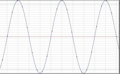
I think there is a mis-statement there. The point is when you do a sinc interpolation of sampled data there can be interpolated values larger than each adjacent value. Think for a second sampling a 20K sine at 44.1K you do not (can not) catch all the peaks + or -. There is no violation of Nyquist, the perfectly interpolated signal is the 20K sine wave generated from the original samples. Picture is 5K sampled at 44.1K at bottom the peak is greater than adjacent samples.
I ran across this effect in generating psuedo-random noise and then interpolating it to a higher sampling frequency, there is a SLIGHT shift in the expected crest factor distribution.
Attachments
Last edited:
The reasons given have always been for input or output filters' audible artifacts...... example - brick wall filters close to audio --- so fix that with other techniques. But its a moving target in many cases. The analog or digital, and besides amps, has been the filters' audible effects. This is why I brought in the subject of Group Delay as one artifact.
THx-RNMarsh
THx-RNMarsh
Last edited:
Think for a second sampling a 20K sine at 44.1K you do not (can not) catch all the peaks + or -. There is no violation of Nyquist, the perfectly interpolated signal is the 20K sine wave generated from the original samples. Picture is 5K sampled at 44.1K at bottom the peak is greater than adjacent samples.
I ran across this effect in generating psuedo-random noise and then interpolating it to a higher sampling frequency, there is a SLIGHT shift in the expected crest factor distribution.
Scott
I think that this implies that there will be a measurable level difference btn DAC input and output.
And that such a difference will differ between the case of a HF input signal that was captured in 24bit/44.1k and the case of the same HF signal captured in 24bit/96k or better 24bit/192kHz.
What do you say?
I am trying to find a way to observe the presence and measure the effect of “Inter-sample "overs" using steady state signal and available DACs and ADCs.
George
One solution is to offer many filters with different affects.. No less than seven here:
Audiolab Q-DAC filters
THx-RNMarsh
Audiolab Q-DAC filters
THx-RNMarsh
Redbook CD sound compressed and sound lacking in life or transient details or less clarity in upper freqs .... is this why?
Same reason as LPs- compression by the mastering engineer. The format has nothing to do with it.
Scott
I think that this implies that there will be a measurable level difference btn DAC input and output.
What do you say?
No, this implies loss of information. BTW "level" at both DAC input and output makes no sense, one is bits the other is voltage.
Redbook CD sound compressed and sound lacking in life or transient details or less clarity in upper freqs .... is this why? And why many like certain type filters over others?
They don't to me and many others.
"Perfect sound forever!" I have heard this phrase for the last 35 years or so. There are always people who accepted CD level digital wholeheartedly from its very first incarnation such as the F1 video tape digital recorder. When some of us teased one of these 'very bright engineers' as time went on, and early mistakes were found and fixed, then he said 'Even more perfect sound forever!' '-) And so it goes. Some accept CD level of audio quality, and others strive to improve on it. It is been that way for several decades now.
- Status
- Not open for further replies.
- Home
- Member Areas
- The Lounge
- John Curl's Blowtorch preamplifier part II