That would be Madsen and Soerensen, TI Applications Report SLEA049, June 2005. Plucked from Cordell, page 600.Did you ever read TI's appnote about PSRR measurements of classD amps? I have linked to it on my blog - most enlightening. It was Bob Cordell who put me on to that, I think from the classD chapter in his amp book.
No, I haven't read it. It may be distantly relevant here, but based on the magnitude of the effect with non-switching amplifiers, I suspect it will be a very small effect. But it is intriguing. I take IM distortion very seriously.
TI almost hired me to do a hybrid higher-power digital-modulator-based switchmode amplifier, so they, while working in Denmark on integrated solutions, could displace evil D2 Audio from Harman products (the adoption of D2 Audio amps being one of the stupidest decisions for a receiver ever made in the hallowed halls of pre-Paliwal Harman). I would have probably done, by and large, what TI eventually had to do to improve---wait for it---Power supply rejection!
I would have had my chance, but my cost estimate was a factor of about four over what their undisclosed but hinted-at budget was. The result was another waste of time.
I do this a lot. I would say I did this a lot, but I am, sadly, still likely to do it again. But life goes on.Dilbert strikes again.
The re-question is --- Not what arb figure to design psrr to..... rather what is the min needed to be designed to given typical PS used for PA in order to be inaudible in typical system?
This is in the interest of some topologies having inherently lower power rejection than others.... VFA vs CFA. And, does that inherently lower number really matter if it is sufficiently high. What is sufficiently high, listening-wise?
THx-RNMarsh
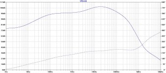
Is this sufficiently high enough, listening-wise, and this is CFA?
Attachments
That would be Madsen and Soerensen, TI Applications Report SLEA049, June 2005. Plucked from Cordell, page 600.
http://www.ti.com.cn/cn/lit/an/slea049/slea049.pdf
But I think abraxalito is talking about this one (which happens to be in line with your way of thinking about using THD to access PSRR) :
http://www.eetasia.com/STATIC/PDF/200909/EEOL_2009SEP04_ACC_TA_01.pdf?SOURCES=DOWNLOAD
George
Of course this is just output stage power supply sensitivity. But yes, it suggests that if one is getting a lot poorer than that, it's probably not on account of the output emitter followers coupling from their collectors to their emitters.
By the way, larger and faster parts like the venerable 2SA1302/2SC3281 have even better rejection, but it does not extend to quite as high frequencies.
Ahh, Got it - just OPS pair.
Is this sufficiently high enough, listening-wise, and this is CFA?
A CFA PA with more than -100db to 100KHz sure looks good to me.
THx-RNMarsh
So i would like to know, if it is true, that the impedance of a speaker drops down when feed with a short and strong impulse.
We have a swiss company, Rowen, who claims this and a guy from Dynaudio told me this also once. They talk abouth 10 % of the nominal impedance, but i don't understand enough what happens.
The voice coil inductance can induce phase shifts as well as the system mass so worst case it lowers it. I will see if I can find a curve where it dips below the DC resistance. I used to have a classic case but I think it got lost in a computer crash.
The other example data I used to keep with that was the one that showed the acoustic center was not at the voice coil. Won a few bets with the pair.
But the drivers I play with are all high efficiency types.
One of the nifty differences is that transducers for efficiency should not have flat frequency response. For a given cone size as you move it the same distance but more often the output should rise.
Sorry for the late reply. Let me approach this from two different angles to explain why it is extremely unlikely that a driver's impedance dives below its Rdc.
First of all, take a look at the physics involved. If a driver moves in the same direction as it is forced by a current through the VC, the VC generates a voltages that is of opposite sign as the voltage which initially forces the current through the VC. The result is an apparent increase in VC resistance.
In order to generate an apparent decrease in VC resistance, the VC has to move in the opposite direction as the current through the VC forces it to move. There is no external force which can cause this to happen. Closest in physical terms is the tuning point in a bass reflex enclosure, where a maximum breaking force is exerted on the driver because the air pressure inside the enclosure is in counter phase with the driver. This is the point where the drivers impedance approaches its Rdc.
Another way of looking (but it boils down to the same) is that it requires a lot of energy to virtually decrease the impedance of the driver. Take an 8 Ohm speaker fed by 8V, which at its Rdc will draw 1A for a total of 8W. Now suppose that through back EMF, the impedance of the driver dives to 4 Ohm. The driver will now draw 2A, and the amp will deliver 16W into the driver. Of these 16W, only 8 will be dissipated by the Rdc. The other 8 will have to be dissipated in another way, and it is by expending the energy required to generate the back EMF. In other words, in order to lower the Rdc, the mechanism causing this to happen would cost as much energy as it would draw additionally from the amp. There is no mechanism that can input that much energy into a driver.
Last edited:
I worked with the 'S' company for a year in Tokyo to design in some 100W RMS class D amp IC's.
The cost pressure on those 'boom box' products was incredible. Lots of corners cut on things like transformers - a 150 VA unit cost them about $3.50 and filter caps (2 x 2200uF35V) around 12c a piece.
I went up to the 23rd floor in the Oval building in Shinagawa where they had their audio design group to do a 'sound taste' test on one of their units fitted out with our chips.
The room was full of esoterica - ML power amps, B&W Nautilus speakers, 802's plus an assortment of Dali's etc and some very nice looking high end stuff of their own.
Anyway, they pulled out some speaker stands, put the boom box speakers up on them and connected the receiver to them and sat down for a serious listening test.
We had all sorts of comments back about the bass not firm enough, treble ok, mid range too recessed etc. They played some real dance music crap - terrible stuff compressed to hell.
I thought to myself 'how can you hear this on lo-fi single drive unit speakers and a 150VA transformer with a totally sub-optimal filter bank?' My overwhelming feeling was that they were just going through the motions.
Anyway, we got the business. About 6 months later we get a call in our Malaysia office - there's a problem with your chips - a whole lot of them are not performing.
The app engineer soon found the issue. The speakers were supposed to be 3 ohms and a whole batch of 4 ohm units has been mixed up in the production batch. Problem solved.
These products by the way were targeted at the South Amercian market - big business over there for them at the time.
These kinds of products are absolutely designed to a price - and the biggest area of skimping was the PSU in my view . . . you see the same thing at the 'P company, Samsung, LG.
Later on we exited that business and focused on mobile.
(to prevent the rail pumping problem, the input of one channel is inverted and then the speaker outputs on that channel reversed)
Last edited:
But I think abraxalito is talking about this one (which happens to be in line with your way of thinking about using THD to access PSRR) :
http://www.eetasia.com/STATIC/PDF/200909/EEOL_2009SEP04_ACC_TA_01.pdf?SOURCES=DOWNLOAD
Absolutely right George, I hadn't picked up that Brad cited another one.
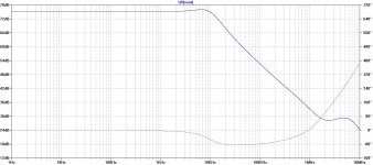
For CFA, cap multiplier (CM) + high loop gain = high PSRR
The CM confers at least another 30~40 dB PSRR. I have some photos in my e-Amp write up with scope shots before and after the CM that demonstrate this.
No cap multipliers in that CFA whose PSRR I presented, just RC filtering for the IPS.
This is PSRR with no power filter caps at all.
Attachments
Last edited:
For CFA, cap multiplier (CM) + high loop gain = high PSRR
The CM confers at least another 30~40 dB PSRR. I have some photos in my e-Amp write up with scope shots before and after the CM that demonstrate this.
Not trying to split hairs, but a CM doesn't change the PSRR. It decreases the power supply noise/ripple. And thus, less of it gets to the amp output. But the amp PSRR stays as it is.
A minor point but worth making IMHO.
Jan
Nice, thanks.I have yet to find a driver motor unit that is itself a difficult Z load.
In all cases, the low Z values I’ve measured across the terminals of a speaker box are to be attributed to the passive cross over used.
I give you an example
George
Now, recall that this is a steady state single frequency excitation plot.
If music is forcing heavy bass, midrange, and highs, The resultant load will be the paralleling of the three drivers. If you see 8 ohms bass, 8 ohms mid, 8 ohms high simultaneously, the amp will see a load less than 3 ohms. The only saving grace then is the fact that the mids and highs are not very large voltages.
How strange that you should mention that. This is something I've had to look into on one of my designs whereby the B-E junction of the input stage is reversed biased for 'some considerable time' during power on. Its not destructive at the currents involved but it can I believe seriously degrade the noise performance of the device. Better to get it correct in the initial design than for it to surface as a problem at some later date.
We have this problem at work as well. The users tend to go through turn on sequences which are guaranteed to latch component inputs via the scr mechanism (digital), or damage analog ins.
Turning on the input signal to a differential input pair that is unprotected will basically guarantee E-B reverse bias breakdown conduction if the input stage is not designed with appropriate protection.
An employ a long time ago would use NPN's upside down, much better sat voltage. They'd require BVebo, the test system never seemed to damage the componenets that I was aware of. But it was a very controlled test.Not me, avalanching Vbe's creates hot carriers that get trapped in the oxide there is no guaranteed way to perfectly reverse the process. Everything I have seen is empirical type stuff. In general high temp annealing for a while probably gets everything to relax back to normal, I don't know if this has been extensively studied.
Sorry for the late reply. Let me approach this from two different angles to explain why it is extremely unlikely that a driver's impedance dives below its Rdc.
First of all, take a look at the physics involved. If a driver moves in the same direction as it is forced by a current through the VC, the VC generates a voltages that is of opposite sign as the voltage which initially forces the current through the VC. The result is an apparent increase in VC resistance.
I hilited the part. It's important to speak clearly on this, as it does indeed depend on how one looks at the schematic, that of an amp paralleled to the VC, or in series with it. Nonetheless, the EMF generated reduces the drawn current in steady state operation. Which is what you've stated.
In order to generate an apparent decrease in VC resistance, the VC has to move in the opposite direction as the current through the VC forces it to move. There is no external force which can cause this to happen.
Steady state, you are correct.
When the amplifier is trying to brake the system, the math changes.
John
Last edited:
Vacy,
As already mentioned you are looking at impedance as a constant for any given frequency. If we consider it to be influenced dynamically the issue changes.
In the case of an impulse into a transducer, the transducer with adequate damping factor may stop moving with the cessation of the current, but the air in the enclosure will not. This is sort of like tapping on the loudspeaker cone while measuring impedance. Now as most consumer drivers are low efficiency I can see this impulse mechanism dropping the impedance a bit below the DCR.
However where we really disagree is " There is no mechanism that can input that much energy into a driver." As you know we work in quite different environments. In my world there is a mechanism that can impart more energy into a transducer than the audio power amplifier! We refer to it as "Wind." I did a stadium where the amplifiers were only rated down to 4 ohms. I had to change them to ones that could drive much lower even though the rated impedances were above that. When the wind kicked up things sounded quite off.
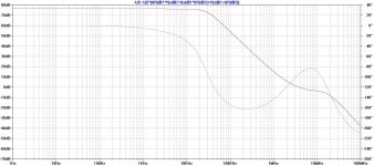
I put here the Loop Gain plot and PSRR plot of the same amp showed before with all power filter caps removed (not of course for the LG plot).
It is interesting to see how the PSRR plot refleks the Loop Gain plot.
It is interesting to see how the PSRR plot refleks the Loop Gain plot.
Attachments

- Status
- Not open for further replies.
- Home
- Member Areas
- The Lounge
- John Curl's Blowtorch preamplifier part II