Yes, I prized having a Triplett 310 VOM with a 15V battery for doing finger-leakage base current injection while looking at collector-emitter "resistance", to verify that a transistor had decent beta. There were cases where a part that tested well for collector-base and base-emitter diode drops had almost no current gain.I've heard that too (ohmmeter testing) although I can't recall where I read it, and... you've just reminded me of somethingthe AVO 8 comes to mind with its 15 volt battery on high ohms range.
I remember at college and how we had to test and sort transistors into functional/non-functional and NPN/PNP. Back then they were all metal BC107/BFY50 packages or TIP41/42 with numbers rubbed off and I had learnt the trick of using an AVO on high ohms to see if the device was NPN or PNP simply by observing reverse leakage from C-E when reverse biased. Get the polarity correct from that and one more test of a wet finger dabbed across C-B saw the needle swing hard over to zero if the device was good.
My classmates were amazed I could sort them all in seconds while they all followed the standard 'diode checks' across every junction.
Happy days
Yes, it is a serious degradation mechanism. Motchenbatcher cautions about testing low noise bipolars with an ohmmeter in his first book. He also mentions that the damage done can be annealed out by high temperature baking, although this is scarcely practical!
Are there details on what transistors specifically he had tested and what the meter did to fry them? What current it takes?
IIRC Scott mentioned one way to reverse it was to apply high base current?
IIRC Scott mentioned one way to reverse it was to apply high base current?
Not me, avalanching Vbe's creates hot carriers that get trapped in the oxide there is no guaranteed way to perfectly reverse the process. Everything I have seen is empirical type stuff. In general high temp annealing for a while probably gets everything to relax back to normal, I don't know if this has been extensively studied.
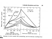
Without further brutalization of the book, or a decent document camera, I can't get satisfactory scans of all the several pages, but here is the beginning of the discussion and the first figure. These are from the first book by Motchenbacher and Fitchin, Low-Noise Electronic Design, ISBN 0471619507. A second similar book with Connelly is around somewhere but I don't recall if the same discussion is in it.Are there details on what transistors specifically he had tested and what the meter did to fry them? What current it takes?
IIRC Scott mentioned one way to reverse it was to apply high base current?
Yes, the section reports that the annealing was done by running 400mA of forward base current through the device, and that, although of interest, is not a practical solution
PS: a paper by McDonald is referenced which may have more details about the degradation and restoration, Avalanche-Induced 1/f Noise in Bipolar Transistors, IEEE Trans. Electron Devices, ED17, pp. 134-136.
Attachments
Last edited:
I did a bit of sim with a voltage-source-driven complementary emitter follower output stage. I used the ancient 2N3055 and MJ2955 (as used in the NAD 3020) with 200 milliohms in each emitter and voltages across the bases to establish a fairly rich 200mA quiescent bias, and run from +/- 30V rails, and with an 8 ohm resistive load. The power supply rejection was about 80dB out to a few hundred kHz, with the negative rail having somewhat better rejection than the positive.
For a 1V peak input at 1kHz, the distortion out to 15th is predicted to be 108ppm. Due to less than perfect complementarity, the dominant component is second harmonic (at about -79dB, with third at about -92dB, and higher harmonics much lower).
I added 2 ohms in series with each supply. For 1V p-p inputs this raised the 1kHz distortion by a very small amount (to 110ppm). At high signal voltages the 2 ohm Rs cause the collectors to crash into the emitters as it were, and of course then the distortion rises precipitously, while the zero impedance supplies version keeps on going for a while.
Again, note the assumptions: no thermal distortions, and voltage source drive. But it does confirm what one would expect, that due to the relatively high impedance at the collectors, the sensitivity to power supplies' noise and impedance below overload is pretty small. The voltage source drive is unrealistic and conceals other mechanisms like base width modulation that will degrade performance for more realistic base drive. But we can come close.
You say PSRR of -80 dB out to a few hundred KHz. That is a very good result on a power amplifier IMV
Re the reverse bias problem - I put a clamp diode from each supply rail to ground after the filter resistor for just such an eventuality. You can never guarantee the rails come up together, or smoothly. Further, if you get a fault, its possible to blow a lot of small signal devices if one of the rails gets pulled to the other.
I suggest the inexpensive 6A4 for this job (datasheet). 6 amps forward, 400 volts reverse, max forward surge current = 400 amperes, axial lead thru-hole package "R6".Re the reverse bias problem - I put a clamp diode from each supply rail to ground after the filter resistor for just such an eventuality. You can never guarantee the rails come up together, or smoothly.
If 400 amperes of max forward surge current simply isn't enough for you, its big brother device (the 10A04) comes in the same package and is rated for 600 amps IFSM.
You can't answer that in isolation. As mentioned before, the crap that ends up on the output of your amp is the product (quite literally) of PSRR and psu noise. The two are interchangeable and a compromise has to be selected.
The only meaningful requirement is the S/N ratio from the psu point of view. if you want, say, 100dB, it can be reached with really high PSRR paired with a so-so psu, or a really good psu paired with so-so PSRR, or something in between. It's up to the designer where he spends his money.
Jan
The re-question is --- Not what arb figure to design psrr to..... rather what is the min needed to be designed to given typical PS used for PA in order to be inaudible in typical system?
This is in the interest of some topologies having inherently lower power rejection than others.... VFA vs CFA. And, does that inherently lower number really matter if it is sufficiently high. What is sufficiently high, listening-wise?
THx-RNMarsh
Last edited:
Re: the saggy/soggy power supply discussion.
Typical Sony/Panasonic etc consumer all in one shelf systems run lousy/under rated power supplies.
In the case of these type systems, noteworthy is that these systems effectively soft limit/compress when running into overload but don't get nasty.
Witness the neighbours' party/bbq etc where the sound coming 'over the fence' is reasonably loud but not offensive.....just squashed and lacking dynamics but not badly subjectively distorted.
Ditto with my (tweaked) Behringer active speakers with active limiting....up to their limit they are fully hifi and 'pushing' them causes greater 'density' but no nasty clipping artifacts.
So, amplifier stages with saggy power supplies, decent PSRR and good overload behaviour are not all bad.
Not good for hifi reproduction, but good for neighbourly relations.
Dan.
Last edited:
Of course this is just output stage power supply sensitivity. But yes, it suggests that if one is getting a lot poorer than that, it's probably not on account of the output emitter followers coupling from their collectors to their emitters.You say PSRR of -80 dB out to a few hundred KHz. That is a very good result on a power amplifier IMV
By the way, larger and faster parts like the venerable 2SA1302/2SC3281 have even better rejection, but it does not extend to quite as high frequencies.
Some look-see into the compensation technique's affect on PSRR...... Miller Comp (Cc) may affect one polarity psr more than the other polarity.
Also, look-see common-mode gain is non-linear, additional distortion is generated which is not suppressed by the feedback.
When the PA has to drive a large load and when the supply line Z raises, the finite PSRR causes similar effects.
THx-RNMarsh
Also, look-see common-mode gain is non-linear, additional distortion is generated which is not suppressed by the feedback.
When the PA has to drive a large load and when the supply line Z raises, the finite PSRR causes similar effects.
THx-RNMarsh
Last edited:
I agree . . . PSRR in modern opamps is generally beyond reproach.
I've not found that to be so in practice, if by 'beyond reproach' you mean 'audibly transparent'.
Agreed - excellent work done by KCP there.Only think to be careful with is decoupling on opamps supplies - Kendall has that one covered.
By the way, larger and faster parts like the venerable 2SA1302/2SC3281 have even better rejection, but it does not extend to quite as high frequencies.
Do you have any measurements, plots for that? I'd be curious about seeing the details.
Incidentally on the sims you did for distortion, I'm not sure that measuring distortion changes is going to tell you a huge amount about output stage PSRR. The dominant frequency on the supply is probably the fundamental - so try a higher frequency source to 'ping' the supply and see how much of that second frequency bleeds through to the output while the OPS is reproducing the first. I did this in LTspice and got interesting results - the PSRR varies over the cycle.
Last edited:
The power supply rejection is not based on a distortion measurement, simply the output level relative to the signal on a given rail. The distortion measurement was a separate simulation, something of interest but not the main focus. And these are sims, and are at the mercy of the quality of the device models.Do you have any measurements, plots for that? I'd be curious about seeing the details.
Incidentally on the sims you did for distortion, I'm not sure that measuring distortion changes is going to tell you a huge amount about output stage PSRR. The dominant frequency on the supply is probably the fundamental - so try a higher frequency source to 'ping' the supply and see how much of that second frequency bleeds through to the output while the OPS is reproducing the first. I did this in LTspice and got interesting results - the PSRR varies over the cycle.
EDIT: I probably could dig up some of the big Toshiba parts and do a measurement, but I'm fairly busy and bench space is scarce at the moment.
Last edited:
The input (the bases, separated by constant voltage generators setting the bias and adjusted for a ~zero voltage out at the emitters) were tied to common.Its not that urgent, don't spend any extra time on my account.
When you did the PSRR sim for the 3055/2955 pair did you have them driving any signal into the 8R load? Your figures sound too good to be true so I would guess no.
I'm not sure about how driving another signal in would make the figures for PSRR more realistic. But it would certainly make things more difficult to parse.
- Status
- Not open for further replies.
- Home
- Member Areas
- The Lounge
- John Curl's Blowtorch preamplifier part II