I have even better: the unabridged paper datasheet from the epoch they were released (thank hoarders like me!).
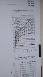
It is true that the characteristics are seriously sloped, considering that they are HV transistors, but at that time, simply making complementary video transistors was a feat in itself, and honestly on a video picture nobody notices moderately severe amplitude distortions.
Of course, the datasheet makes no mention of Vaf or any other spice parameters, but it can be guesstimated from the graphs: I reckon it is a little over 50V worst-case for Ib=5mA.
These are typical curves, and maybe in the spice model they went for the worst-case?
That said, they probably refined the process in the subsequent years, but they kept the initial model based on the historic type; they probably didn't care too much about spice, because they have their own in-house modelling: Mextram
This is Siemens from 1975/76 probably predecessor of BF469. Vaf does not looks so bad at collector current below 30mA.
Attachments
Last edited:
Not to mention the "hand matched" competitive edge.
A couple of years ago I demonstrated (both built and simulated) that the complementary JFET input with trims on the current ratios of both pairs obviates any need for matching. Not that anyone cared.
(obviously the Extreme UVL Patrick did)
Haven't looked recently, I've seen pictures of piles of SK170's with Idss marked to 4 digits on tiny little stickers.
I did buy a pile of the little metal clips to hold pairs in thermal equilibrium. You can choose any two degrees of freedom to trim. If offset and drift are trimmed (possibly a little tedious in practice) servos are not necessary except possibly for huge DC gains.
Last edited:
On another point, if you look at the ideal JFET equations you will see that the cancellation of the quadratic term requires both Vp AND Idss to be the same. This would require exact complimentary pairs not just Idss selection.
Last edited by scott wurcer; 5th September 2012 at 10:09 AM.
Scott, can you pls show trims on the current ratios?A couple of years ago I demonstrated (both built and simulated) that the complementary JFET input with trims on the current ratios of both pairs obviates any need for matching. Not that anyone cared.
Scott, can you pls show trims on the current ratios?
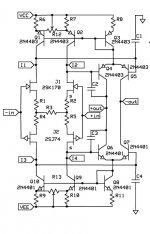
I built some of these (there is more to make up an entire amplifier) to demonstrate simultaneous trimming of Vos and Aol (Aol could be + - or infinite) to debunk the wide open-loop BW folklore. Vos and drift could also be simultaneously nulled.
Attachments
Last edited:
A couple of years ago I demonstrated (both built and simulated) that the complementary JFET input with trims on the current ratios of both pairs obviates any need for matching. Not that anyone cared.
What do you know Mr. Wurcer, hand matching brigs a warm and fuzzy feeling to both the matcher and the matchee beneficiary. Nothing you could replace with cold, dry engineering.
Well, I'll stick to jfet matching. It is relatively easy for me, because I normally use factory matched pairs for my personal stuff. However, I have worked with complementary jfet matchers that are relatively simple in concept and execution, that work really well.
For the record, with the complementary differential jfet input stage, the biggest factor is the same type of device. The automatic resistive self bias will remove a good deal of 'slop' between the n channel and the p channel devices without much problem.
I like servos, they make things easier, and some of my designs could not be made without servos, especially the phono stages with 80dB low frequency gain.
I still believe, all else being equal, high open loop bandwidth is preferred in my best designs, but I can still achieve an A rating with conventional designs like the AD797.
Scott, are you going to the AA meeting tonight? I have to miss it this time.
 I don't have a house in CA anymore. Does offering people an alternative approach bother you that much, maybe I should leave your thread alone?
Last edited:
I find Scott's solution very interesting. I'm not sure how to adjust the pots in practice because I can see what appears to be a continuum of working settings.
Well, you're probably still aiming for the lowest possible deviance in sides to get the matching. So the smallest tweaking away from the center of the adjustment range. Not having boots on the ground on this design, it'd be hard for me to put together an iterative solver in excel to figure it out, but *hopefully* it'd be pretty quick in practice. Safe to assume that once the whole system is warm, the small permutations in bias per side aren't going to cause too much long-term effects.
I find Scott's solution very interesting. I'm not sure how to adjust the pots in practice because I can see what appears to be a continuum of working settings.
Yes it is a search algorithm, as I said, it can be tedious when one parameter is something like temperature drift. In general you can reduce it to a problem with two equations and two unknowns, I posted pictures years ago of trimming the amplifier to zero offset and "infinite DC gain". It is possible to take two measurements and calculate the solution by computing the derivatives and using Newton's method. Genuine NOS JFET's have become very expensive not having to buy extra to get matching saves one money and there are plenty of folks here that are on a budget.
Last edited:
Scott, your alternative is interesting, perhaps a little too complex for my taste, but it's OK. It is the 'myth' word applied to my design criteria that annoys me. You can do it your way, and I will do it mine. Dick Sequerra and I think you need a talking to about this. He can hardly believe what I say that you put up here about open loop bandwidth and other things.
As far as the AA meeting is concerned, I heard a rumor that you were going to show up, but I decided not to go this year because Walt Jung decided not to go. It would have been fun to get you, me, Walt, Bob Cordell, and Ron Quan together over a few glasses of wine. '-)
As far as the AA meeting is concerned, I heard a rumor that you were going to show up, but I decided not to go this year because Walt Jung decided not to go. It would have been fun to get you, me, Walt, Bob Cordell, and Ron Quan together over a few glasses of wine. '-)
^ I'm surprised you can't linearize it based on small perturbation. Depends on how far apart the jfets are, though.
That is Newton's method, linear combination of the first derivative of two variables only. Of course it is not good if the FET's are way far apart, but that is easy to avoid.
That is Newton's method, linear combination of the first derivative of two variables only. Of course it is not good if the FET's are way far apart, but that is easy to avoid.
Derp. Sorry about that. Utter brainfart about model/method definitions. You'd think I would know that given I've made CS assignments where we made a super simple Newton-Raphson solver. I will continue to eat my foot in silence.
Last edited:
Scott, your alternative is interesting, perhaps a little too complex for my taste, but it's OK. It is the 'myth' word applied to my design criteria that annoys me. You can do it your way, and I will do it mine. Dick Sequerra and I think you need a talking to about this. He can hardly believe what I say that you put up here about open loop bandwidth and other things.
As far as the AA meeting is concerned, I heard a rumor that you were going to show up, but I decided not to go this year because Walt Jung decided not to go. It would have been fun to get you, me, Walt, Bob Cordell, and Ron Quan together over a few glasses of wine. '-)
It would be fun but I can't justify the expense without having my own place to visit, The analog content of the ISSCC has dwindled to a trickle.
Last edited:
I built some of these (there is more to make up an entire amplifier) to demonstrate simultaneous trimming of Vos and Aol (Aol could be + - or infinite) to debunk the wide open-loop BW folklore. Vos and drift could also be simultaneously nulled.
Scott, I've been working on a FET phono stage which could be amenable to that approach (it costs all of two trimpots, such complexity!). Is there an advantage to having the trimmer be between the two current-setting resistors as opposed to having on fixed and one variable current setting resistor?
- Status
- Not open for further replies.
- Home
- Member Areas
- The Lounge
- John Curl's Blowtorch preamplifier part II