For audio, a Vaf of 20 isn't very good, I wasn't meaning to imply anything else. It wasn't a judgement on NXP as a whole. Those devices would work well in other applications for sure.
All other parameters are as good as Sanyo or Toshiba video transistors. I suppose Vaf is as good too, just bad models?
We don't know, so let's not make any conclusions without evidence.
Someone with transistor tracer could do that.
I have even better: the unabridged paper datasheet from the epoch they were released (thank hoarders like me!).Someone with transistor tracer could do that.
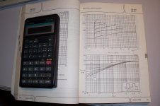
It is true that the characteristics are seriously sloped, considering that they are HV transistors, but at that time, simply making complementary video transistors was a feat in itself, and honestly on a video picture nobody notices moderately severe amplitude distortions.
Of course, the datasheet makes no mention of Vaf or any other spice parameters, but it can be guesstimated from the graphs: I reckon it is a little over 50V worst-case for Ib=5mA.
These are typical curves, and maybe in the spice model they went for the worst-case?
That said, they probably refined the process in the subsequent years, but they kept the initial model based on the historic type; they probably didn't care too much about spice, because they have their own in-house modelling: Mextram
Attachments
See Syn08's website for inspiration and Dennis Colin's LP797 for a good primer.
more l8r")
The cache would be lost if the parts were available.
It's a shame they don't show lower base current curves. For some Sanyo parts at 1mA the output conductance is much lower, compared to 5mA and up. See the datasheet for the 160V Vceo 2SA1507 and 2SC3902 for example. In fact the slope is not monotonic, but that may have been a drafting error.
In any event, for high Z at a collector, control electrode recycling is your friend, if you can manage the stability issues.
In any event, for high Z at a collector, control electrode recycling is your friend, if you can manage the stability issues.
The cache would be lost if the parts were available.
Not to mention the "hand matched" competitive edge.
The cache would be lost if the parts were available.
Until I just read Waly's response, I couldn't make heads or tails out of what you were saying. Accents make a difference. Haha.
And spelling. I was similarly baffled. The word intended is cachet.Until I just read Waly's response, I couldn't make heads or tails out of what you were saying. Accents make a difference. Haha.
And spelling. I was similarly baffled. The word intended is cachet.
Or cache, according to m-w: a hiding place especially for concealing and preserving provisions or implements
It's a shame they don't show lower base current curves. For some Sanyo parts at 1mA the output conductance is much lower, compared to 5mA and up. See the datasheet for the 160V Vceo 2SA1507 and 2SC3902 for example. In fact the slope is not monotonic, but that may have been a drafting error.
In any event, for high Z at a collector, control electrode recycling is your friend, if you can manage the stability issues.
I can see on the lowest curve it starts to level out but not by much. And think about it, it takes >30V already to get out of quasi-saturation, so your last 30V of headroom will still suffer.
Base current recirculation does work, but it can be a lot of work. You will need several more components, and you will also have to set it up so it won't impact PSRR. And the stability problems - I wonder how many people actually fully understand that issue.
Few. A lot of conjecture but not many hard results in the pertinent threads in diyaudio. John Addis worked with the approach a lot, and in one instrument used a very high ft device as the auxiliary transistor. He told me he found it necessary to introduce a small R-C network in the emitter of the main device to prevent GHz oscillations. This did show up in simulations, not sure what the software package was.And the stability problems - I wonder how many people actually fully understand that issue.
I find at least a little external C to common is needed at the output collector, which is already often present in the rest of the circuit.
The other problem is that the efficacy of the Boxall configuration is limited by the auxiliary transistor's collector current being shared between the main transistor emitter impedance and whatever is in the emitter. If you are really after the ultimate in performance it's well to have the external impedance in series with the emitter large, which is to say even more parts and more voltage sacrificed. But it can work very well indeed.
Familiar observations!
One problem with the Boxall pair approach I found was that it tends to lead to continually increasing impedance at the collector. I had a design in simulation where the drivers were bootstrapped to eliminate Cob and I had a 1pF capacitor to ground at the collector, which stabilized the whole amp.
I think it would have worked, but the idea of parastics made me nervous and I eventually discovered another approach that results in less parts and better stability, without a single Boxall pair. I made a working prototype and I was pleasantly surprised by how trouble free the compensation turned out.
Although perhaps to my detriment, I want to at least be the first one to release the kit before I talk about that idea publicly.
Thanks a lot Elvee.
I spy 10V over 10mA which means collector impedance is 1k or a bit more at higher voltage. Not very good at all. I would want something more like 100k.
What did I tell you Bonsai?
Nothing at all. I am not questioning the device performsnce - merely the fact that you picked a very old part and expect characterizations that were never published.
As noted, for TV/monitor applications, VAF is of little consequence and at the time these were released, Philips would have been the largest supplier of semi's for that market.
a very old part
BF469/470/471/472 even predate '79
(Philips was one of few semi manufacturers to include full Vce/Ic graphs from which to extrapolate Vaf back then, btw)
And spelling. I was similarly baffled. The word intended is cachet.
Yes dropped the t Soooory.
- Status
- Not open for further replies.
- Home
- Member Areas
- The Lounge
- John Curl's Blowtorch preamplifier part II