Well we went almost three days without any demeaning or nasty comments.
Almost..... they are just warming up IMO.
Yes,we know why and what causes the 20KHz on the sq-wave. I dont care..... it is on the signal going to the analog pre and/or PA and speakers. I'm stopping right there. 'Cause there is more.
So what if you band limit the input to the ADC of the recorder? Same results?
No.
You need a LPF on both ends... record and playback (yes, for different reasons).
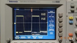
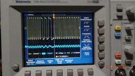
The signal generator I am using for this allows me to 'filter' the sq wave. That is, I can control the rise time and the fall time (independently, if desired). When I reduce the effective BW on the Input and record and burn and playback - we get this at the output to send to the analog amps:

Cheers. Time for an eggnog intermission.
THx-RNMarsh
Last edited:
The 'ripple or ringing' - like- new added signal is described from traditional analog view.
Only because low pass filters that steep are exceedingly rare in the analog domain.
I'll bet money that a CDP 101 which had analog (LCR) brick wall filters does something very similar, but with a lower corner frequency because it had that much poorer of a filter.
As others have pointed out, this is the Gibbs phenomena which is a mathematical phenomena and therefore not restricted to either the digital or analog domain. Its cause is very similar in both domains, but the cause (a really mathematically ideal sharp cutoff) is itself rarely implemented by purely analog means because of the necessary expense and complexity.
It is from the ripple of the sharp cut-off LPF (20KHz) design.
As a rule, the ripple of typical sharp cut-off LPF (22.05 KHz) filter is tremendously smaller - often a fraction of a tenth of a dB.
Better filters with much lower ripple level beyond cut-off and still not introduce audible group delay is needed. Dont know if that Must cost more.
In band ripple can be reduced as low as you want to if you want to invest the necessary hardware, which is stages in a shift register if its a digital filter.
The ripple due to the sharp cutoff can be managed but usually at a cost in the quality of the cut off.
I'm of the opinion that many real world digital filters may go overboard in terms of rapid cut offs and narrow transition bands, but even a good psychoacoustic compromise is going be pretty narrow, pretty sharp and is going to show some evidence of the Gibbs phenomena.
The 'scope trace shows that the ringing is at about 22 KHz, and within reason, ringing that high is well known by people who carefully test such things to be psychoacoustically benign.
Yes,we know why and what causes the 20KHz on the sq-wave. I dont care..... it is on the signal going to the analog pre and/or PA and speakers. I'm stopping right there. 'Cause there is more.
Of course, it's there. But only if you're trying to feed a square wave to your adc-dac chain. What's the point ? The ADC-DAC haven't been designed for that.
See above # 26862
-RNM
Hard to turn into effective action.
How about one of those pretty little links that right clicking will set up for you?
That's a bit short.
Could you please state your point clearly because even that post 76862 is fairly cryptic.
What's the problem with the scope shot shown in that post ? Compared to the picture of the signal of the generator a few posts back, it seems fairly clean. There's an hint of overshoot but then it's lost in the HF noise.
It would be more clear if you posted both what happens when you feed your adc an ideal square wave (what you said you would do) and what happens when you limit it.
Of course, it's there. But only if you're trying to feed a square wave to your adc-dac chain. What's the point ? The ADC-DAC haven't been designed for that.
The ADC is supposed to be preceded by an effective low pass filter to eliminate aliasing. Convention is that its slope approximates brick wall and just under the Nyquist frequency. For 44.1 KHz sampling This is just about ideal for protecting any weaker analog components downstream (e.g. a power amp).
In practice these filters can be highly effective attenuators of ultrasonics,
If the recording is made at a higher sampling rate, the downsampling procedure is supposed to have similar filtering.
Any ringing of either filter is supposed to be at or below 22.05 Hz.
RNM,
One issue is that an oscilloscope does not show the whole picture. In a signal that is really ringing, energy will continue even after the source should have stopped. In a sampled and reconstructed waveform you can see the same arifacts, except they will stop exactly with the rest of the signal.
What the oscilloscope does not show is if a reconstructed signal is also ringing. Those artifacts would be hidden by seeing the expected display.
The best way to look for ringing is with a waterfall of the spectrum.
So you can have apparently the same oscilloscope display and have it sound different because you are limited to only part of the whole picture.
Now the issue of does a better reconstruction of the original waveform improve fidelity is a similar but different issue. There certainly are folks who have done better reconstruction approaches and found they were pleased with the result.
Now as to your quest to see how HF splatter degrades sound, I am of the OPINION that it will affect all systems if the issue has not been addressed in the design. Those who count on the source to handle the issue will of course be limited in final results.
Last edited:
Water fall plots are great.... but not for right now. I have several tools which can do that.
The ripple on the sq wave I will call a ring of 20Khz freq. Just because it is familiar term. In analog, it would be from damped excitation of a resonance condition.
But, now who would look at the input port when there was no signal applied to the input? I would. If there is anything shown besides noise, that can and may be sampled along with the desired signal. Once you have done that -- contaminated input signal -- once the 1 and 0 are recorded and from there it is replicated in bit perfect fashion (error correction etal). So beside cable HF pickup, grounding etc etc. Is there anything inside that could couple to the sensitive ADC input circuitry?
Again here is what I pickup on open inputs. Lets hope 100% is gone with signal source Z termination;
Left and Right inputs:

Looks like some internal shielding is needed and cross-talk minimized.
Its not what is supposed to be there or what is suppossed to happen.... it is what we actually have in this Mastering machine. No doubt DAW and other systems have similar imperfect issues. You have to measure it to know how good it is. And, not always in a politically correct way.
THx-RNMarsh
The ripple on the sq wave I will call a ring of 20Khz freq. Just because it is familiar term. In analog, it would be from damped excitation of a resonance condition.
But, now who would look at the input port when there was no signal applied to the input? I would. If there is anything shown besides noise, that can and may be sampled along with the desired signal. Once you have done that -- contaminated input signal -- once the 1 and 0 are recorded and from there it is replicated in bit perfect fashion (error correction etal). So beside cable HF pickup, grounding etc etc. Is there anything inside that could couple to the sensitive ADC input circuitry?
Again here is what I pickup on open inputs. Lets hope 100% is gone with signal source Z termination;
Left and Right inputs:

Looks like some internal shielding is needed and cross-talk minimized.
Its not what is supposed to be there or what is suppossed to happen.... it is what we actually have in this Mastering machine. No doubt DAW and other systems have similar imperfect issues. You have to measure it to know how good it is. And, not always in a politically correct way.
THx-RNMarsh
Last edited:
I hope you or others do their own similar tests. I/O noise sources and remedies within the digital to analog area. Not only base band signal region.
For this machine, 600 Ohms would be the assumed Z. Who knows what others have/use. Dont over-look the obvious. That ADC input must be scrupulously clean before signal applied. Once it goes to 1 and 0's you cant fix it.
These sorts of things go a long way towards why CD has not lived up to its promise for many; How the unwanted HF noise/freqs affect analog should be reduced. preliminary removal via passive filters on I/O has shown this is a fruitful direction to closing the gap of CD vs HD downloaded files.
THx-RNMarsh
Last edited:
Useful data about the supposed failing of digital would show how this noise actually ends up in the digital file. Of course there's noise at the inputs. Is there noise at the output of the ADC ? That's what truly matters.
You apparently have access to plenty of good measurement gear, why stop halfway in your tests ?
You apparently have access to plenty of good measurement gear, why stop halfway in your tests ?
00940. yes that too can be done. Like water-falls. And, somethings i just keep info and tests to myself. But, I just gave you the bottom-line... use filters on ADC input and DAC output.... beyond what has been done in many cases. Unless the product has successfully cleaned all this HF stuff up. But, you won't know until you test for it.
FWIW ... Billshurv... in this unit... 600 Ohm Z across ADC input only drops HF signal on input by 10% or about 1 dB. And if you look at what I previously showed you, yes there is a lot of HF in the DAC analog output.
Next, I'll get my jitter analyzer running and look at some things.
THx-RNMarsh
FWIW ... Billshurv... in this unit... 600 Ohm Z across ADC input only drops HF signal on input by 10% or about 1 dB. And if you look at what I previously showed you, yes there is a lot of HF in the DAC analog output.
Next, I'll get my jitter analyzer running and look at some things.
THx-RNMarsh
Last edited:
Well, many different filters arrangements, each one with pros and cons. Butterworth, Chebyshev, Bessel, Elliptic ...:Christophe,
I understand that typically the input filter is a simple RC network to band limit the input to the amplifier. What happens when you use a higher order filter such as a fourth order filter and lower the upperfreq. set point say to 50Khz instead of 100khz, can you do that and still keep a flat input up to the 20khz range or does this introduce other problems I'm not aware of?
http://nf.nci.org.au/facilities/software/Matlab/toolbox/signal/filterd5.html.
http://www.idc-online.com/technical_references/pdfs/electronic_engineering/Types_of_Active_Filters.pdf
On my opinion, there is no reason to limit abruptly the input of an amplifier: 6 db/oct, with CF depending of the amp bandwidth is good enough to ensure the slewrate of any signal never reach the one of a good amp, without introducing major phase shift or level attenuation at 20KHz..
Last edited:
RNM, how much of that grass riding on the waveforms is oscilloscope noise?
Hi.
See #76842... the before data
THx-RNMarsh
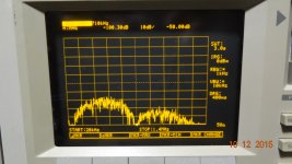
Before this was the DAC analog output HF noise shown a few days back: Add 26dB to it for probe atten. Hardly at the noise floor and easily amplified further by analog pre/PA.
[You'll have to go back to #76414 for beginning of my thread about extrainiouse DAC junk being amplified.]
 Remember this?
This is also after the internal digital filter. The HF signals (over-sampling, perhaps) are following the 20KHz sharp cut-off LPF filter ripple above cut-off.
THx-RNMarsh
[You'll have to go back to #76414 for beginning of my thread about extrainiouse DAC junk being amplified.]
 Remember this?
This is also after the internal digital filter. The HF signals (over-sampling, perhaps) are following the 20KHz sharp cut-off LPF filter ripple above cut-off.
THx-RNMarsh
Last edited:
- Status
- Not open for further replies.
- Home
- Member Areas
- The Lounge
- John Curl's Blowtorch preamplifier part II