Hi Joshua,
That's great then. Just do your work out of any breezes or direct sunlight. Someone else I know discovered that the hard way.")
I normally measure the beta on a meter (Heathkit IT-18) and do a rough grade on measured gain. Then I test each range. The left overs get run through for the heck of it.
I have found that measuring the gain for matches is not always successful. The really close matches made on this contraption are so tight, any resistors in the emitter leads must be matched also. A mis-match there will throw out the match you made with the transistors. You will see what I mean once you begin experimenting.
The foam covers are made from foam blocks with a oval melted out from a soldering iron (coated with solder!). Make two or more, they travel.
-Chris
That's great then. Just do your work out of any breezes or direct sunlight. Someone else I know discovered that the hard way.
I normally measure the beta on a meter (Heathkit IT-18) and do a rough grade on measured gain. Then I test each range. The left overs get run through for the heck of it.
I have found that measuring the gain for matches is not always successful. The really close matches made on this contraption are so tight, any resistors in the emitter leads must be matched also. A mis-match there will throw out the match you made with the transistors. You will see what I mean once you begin experimenting.
The foam covers are made from foam blocks with a oval melted out from a soldering iron (coated with solder!). Make two or more, they travel.
-Chris
john curl said:RS, the other Parasound amps are most probably not related to my direct input.
Thanks. I'll take that to mean there might be some things left over from JC-influenced genealogy but they're not yours.
Hi Bob (burbeck),
Thank you.

Very kind of you sir.
Anything you tend to use should get some physical protection. Ages ago I built a switch with wires and a lamp. It was a car amp trigger device. It kept falling apart until I mounted everything in a metal box and labeled it. As a side benefit, it didn't get lost all the time either. I learned.
I'm not that good at pretty, but when something looks nice there is some pride attached to that. When I ran a business, I took a jig that Yamaha gave us and put it in a box with filters, switches and three oscillators. I added interchangeable connecting cables to it also. Now I had a jig that looked pretty cool, worked well and saved me hours and hours setting up Yamaha CD players. I still have it. The guys at Yamaha service thought it was pretty cool also. I made money with that jig each few months. It allowed me to burn through a setup in record time. Even warranty rates paid well then!
Another jig tests photo detectors in cassette decks and even tests remotes. It is an IR transmitter / receiver with a 'scope output. That's another tool that really cut down on messing around time. It uses a dual 555 timer (556) and has a few different ends to match the job at hand. Again, it's crammed into a small plastic box.
Hi Anatoliy,
Exactly! That was the primary reason for designing the jig the way it is. All you need is a stable temperature, the foam allows greater temperature changes before the pair is affected. Remember, nothing is perfect. Neither is this.
-Chris
Edit:
The power switch resides on an HP 6236 or 6237 power supply! The IR tester does have a power switch. I'm not sure about the CD player setup jig though.
Thank you.
Very kind of you sir.
Anything you tend to use should get some physical protection. Ages ago I built a switch with wires and a lamp. It was a car amp trigger device. It kept falling apart until I mounted everything in a metal box and labeled it. As a side benefit, it didn't get lost all the time either. I learned.
I'm not that good at pretty, but when something looks nice there is some pride attached to that. When I ran a business, I took a jig that Yamaha gave us and put it in a box with filters, switches and three oscillators. I added interchangeable connecting cables to it also. Now I had a jig that looked pretty cool, worked well and saved me hours and hours setting up Yamaha CD players. I still have it. The guys at Yamaha service thought it was pretty cool also. I made money with that jig each few months. It allowed me to burn through a setup in record time. Even warranty rates paid well then!
Another jig tests photo detectors in cassette decks and even tests remotes. It is an IR transmitter / receiver with a 'scope output. That's another tool that really cut down on messing around time. It uses a dual 555 timer (556) and has a few different ends to match the job at hand. Again, it's crammed into a small plastic box.
Hi Anatoliy,
Exactly! That was the primary reason for designing the jig the way it is. All you need is a stable temperature, the foam allows greater temperature changes before the pair is affected. Remember, nothing is perfect. Neither is this.
-Chris
Edit:
You crack me up!One more little thing: a power switch.
The power switch resides on an HP 6236 or 6237 power supply! The IR tester does have a power switch. I'm not sure about the CD player setup jig though.
the majority of paralleled output stages do that.anatech said:show me any .....designs that work well with no series resistance in the base circuits.
The base sees the output impedance/resistance of the driver's emitter.
The Vbe of each output device is the driver's VEmitter - Output voltage - Vre(of each device).
If Vre of each device is the same, we hope it is, then Vbe of each paralleled output device will be the same.
Without matching for this parameter at the intended bias current, the collector current will not be the same, no matter how close the hFEs are.
A similar situation applies across any LTP. the voltage at the two bases/gates should be the same, The voltage at the emitter/source should be the same, i.e. the Vbe/Vgs should be the same when the LTP is passing quiescent bias.
I found that leaving a window or door open affected the results.Wavebourn said:If you match couple of pairs the absolute temperature don't matter since all of them are in the same environment. I'd suggest to place a cooling fan on the board to keep them even. And to use a grounding bracelet like one that was free addition to Sun memory cards.
I did not insulate the REF+DUT from the environment.
It is very sensitive to the direction of air flow across the thermally coupled pair.
Hi Anatech,
---I'm not familiar with that. Could you give me some more information on how I can read Mr. Taylor's article?---
Drop me an email.
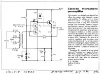
Below is the circuit as published by Taylor.
Hi Jan,
---I believe this scheme is a textbook scheme for an inverting opamp and isn't anything special or inventive.---
I agree, however I was unaware of its use in any commercial product till Audio1's post #733 told us it was used by Barney Oliver.
---I'm not familiar with that. Could you give me some more information on how I can read Mr. Taylor's article?---
Drop me an email.
Below is the circuit as published by Taylor.
Hi Jan,
---I believe this scheme is a textbook scheme for an inverting opamp and isn't anything special or inventive.---
I agree, however I was unaware of its use in any commercial product till Audio1's post #733 told us it was used by Barney Oliver.
Attachments
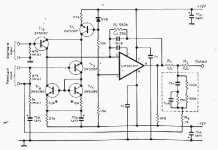
Two more inverting low noise circuits à la Taylor
1.
http://www.aes.org/e-lib/browse.cfm?elib=4959
AES E-Library
A Non Standard Op-Amp Based Mic Preamp Design Meets Studio Quality Noise Requirements
Contemporary transformerless mic preamp design frequently utilizes a state-of-the-art monolithic op-amp supplemented with the descrete input stage. This approach does provide an answer to op-amp's inherent noise problems, but it also violates some of its indispensible properties which opens a number of problems of different nature. The non-standard approach proposed in this paper however, copes with this problem by taking advantage of summation of the uncorrelated noise of n parallel conventional co-amps. This yields a substantial noise reduction, still retaining all of the op-amp's key features intact. Another advantage of this approach is statistical matching of some op-amp's properties thus making selecting obsolete, which can also be suitable for a higher volume production. The paper includes theoretical background with evaluation of some practical implications.
Author: Kovinic, Milan
Affiliation: institute of General and Physical Chemistry, Beograd. Yugoslavia
AES Convention:82 (March 1987) Paper Number:2470
2.
Hartopp
Attachments
forr said:Another advantage of this approach is statistical matching of some op-amp's properties thus making selecting obsolete, which can also be suitable for a higher volume production. The paper includes theoretical background with evaluation of some practical implications.
Massive paralleling of op-amps we like that.
Note, some important things like THD, etc. do not average away.Using low Z inputs generated by feedback goes back many decades. The reproduce stage for the Ampex MR70 used a transformer in a zero Z loading with tubes. The Studer master recorder MK1 reproduce stage used it. The Lohstroh-Otala amp used it in 1972. The JC-3 prototype, 1974, used it.
It just isn't practical in most situations and can be very noisy, if you are not careful.
It just isn't practical in most situations and can be very noisy, if you are not careful.
Hi Andrew,
Now, in a differential amplifier situation, the transistors are looking at current differences. If you want to talk about voltage differences, then you are correct, both bases should be at the same potential. Given that this is not a perfect world, and degeneration resistors may be present also (more uncertainty), when I test for this condition (I do sometimes), I allow that the two measurements may differ by some mV. They commonly do in practice. So even if you had perfectly matched transistors, there may be thermocouple effects that generate a few mV, and then we have those pesky, unmatched degeneration resistors to deal with. Also, look at the differences between a pair of transistors. One may have a VBE of 0.647 VDC and the other may have 0.644 VDC across it. So, you have a difference of 0.003 VDC compared to 0.644 VDC (worst case measurement). The percentage difference is a small number, one that is easily swamped by any differences in beta between the two parts.
So when we look at output transistors, the voltage across the emitter resistors might be (25 mA * 0.22R) 5.5mV, or easily be (25 mA * 0.47R) 11.75 mV. The differences between output transistors is what? 5 mV perhaps? So that will upset current sharing at idle, but the emitter resistors will quickly become dominant and force sharing at higher current levels. Then we also have beta differences as well as tolerance between emitter resistances. While VBE does play an important factor if it's way out, beta and other effects quickly become dominant and take over control on current sharing. In fact, I did use lower bias current levels that give VBE differences greater importance. So even giving you the advantage, other factors still dominate in normal operation.
Again, I generally find that VBE is pretty constant if I match using beta from the same batch. If I look at a batch of devices, the beta is normally more variable than VBE is. That is one reason I'm so happy with the new On-Semi parts, the improved consistency is really noticeable - and appreciated.
-Chris
The entire quote is referring specifically to input pairs in a differential configuration. Paralleled output transistors are another kettle of fish entirely. In fact, I have a pair of jigs built just for that situation (one for BJT, the other for Mosfets). So let's keep these discussions separate to prevent confusing each other and anyone else who cares to follow or comment.quote:
Originally posted by anatech
show me any .....designs that work well with no series resistance in the base circuits.
Now, in a differential amplifier situation, the transistors are looking at current differences. If you want to talk about voltage differences, then you are correct, both bases should be at the same potential. Given that this is not a perfect world, and degeneration resistors may be present also (more uncertainty), when I test for this condition (I do sometimes), I allow that the two measurements may differ by some mV. They commonly do in practice. So even if you had perfectly matched transistors, there may be thermocouple effects that generate a few mV, and then we have those pesky, unmatched degeneration resistors to deal with. Also, look at the differences between a pair of transistors. One may have a VBE of 0.647 VDC and the other may have 0.644 VDC across it. So, you have a difference of 0.003 VDC compared to 0.644 VDC (worst case measurement). The percentage difference is a small number, one that is easily swamped by any differences in beta between the two parts.
So when we look at output transistors, the voltage across the emitter resistors might be (25 mA * 0.22R) 5.5mV, or easily be (25 mA * 0.47R) 11.75 mV. The differences between output transistors is what? 5 mV perhaps? So that will upset current sharing at idle, but the emitter resistors will quickly become dominant and force sharing at higher current levels. Then we also have beta differences as well as tolerance between emitter resistances. While VBE does play an important factor if it's way out, beta and other effects quickly become dominant and take over control on current sharing. In fact, I did use lower bias current levels that give VBE differences greater importance. So even giving you the advantage, other factors still dominate in normal operation.
Again, I generally find that VBE is pretty constant if I match using beta from the same batch. If I look at a batch of devices, the beta is normally more variable than VBE is. That is one reason I'm so happy with the new On-Semi parts, the improved consistency is really noticeable - and appreciated.
-Chris
anatech said:That is one reason I'm so happy with the new On-Semi parts, the improved consistency is really noticeable - and appreciated.
What about PNP devices?
Hi John,
I normally use 1% metal film, and then hand select them to preserve the match. This is very noticeable, and it explains why in the earlier years why some matched pairs performed well and others not as well.
All that matching is a lot of work, I will say that. However, if it didn't make a difference, I wouldn't do it. Take notice that I don't get excited about wire types, but this I am.
Carbon film resistors are not something I'd use in an optimized input stage at all. If it's a high gain stage, you'll be treated to all kinds of nifty noises. I guess that might be okay for sound effects. I don't think they have gross distortion, not like bulk carbon resistors can. But then again, I tend to go for metal film types, or metal oxide types for less critical locations. The surge capability for metal oxides is quite good as well.
Carbon composition is well known for noise, and also for a voltage dependent component. If we add in humidity that many are / were susceptible to, then why even bother designing the circuit? Too many uncertainties for my liking. They tend to increase in value over many years. The only times I see carbon composition resistors are in RF equipment and old tube amps. I do use them for grid stoppers.
-Chris
Edit: Hi Anatoliy,
What do you mean about PNP devices? They match well between themselves, but you have to be looking at the newer process type transistors. I'm not sure about Mosfets, but that was an IR issue, wasn't it? The very best match between NPN and PNP parts I have ever seen are the MJW0281A and MJW0302A (discontinued - darn! )
)
I normally use 1% metal film, and then hand select them to preserve the match. This is very noticeable, and it explains why in the earlier years why some matched pairs performed well and others not as well.
All that matching is a lot of work, I will say that. However, if it didn't make a difference, I wouldn't do it. Take notice that I don't get excited about wire types, but this I am.
Carbon film resistors are not something I'd use in an optimized input stage at all. If it's a high gain stage, you'll be treated to all kinds of nifty noises. I guess that might be okay for sound effects.
I don't think they have gross distortion, not like bulk carbon resistors can. But then again, I tend to go for metal film types, or metal oxide types for less critical locations. The surge capability for metal oxides is quite good as well.Carbon composition is well known for noise, and also for a voltage dependent component. If we add in humidity that many are / were susceptible to, then why even bother designing the circuit? Too many uncertainties for my liking. They tend to increase in value over many years. The only times I see carbon composition resistors are in RF equipment and old tube amps. I do use them for grid stoppers.
-Chris
Edit: Hi Anatoliy,
What do you mean about PNP devices? They match well between themselves, but you have to be looking at the newer process type transistors. I'm not sure about Mosfets, but that was an IR issue, wasn't it? The very best match between NPN and PNP parts I have ever seen are the MJW0281A and MJW0302A (discontinued - darn!
)anatech said:
Edit: Hi Anatoliy,
What do you mean about PNP devices? They match well between themselves, but you have to be looking at the newer process type transistors. I'm not sure about Mosfets, but that was an IR issue, wasn't it? The very best match between NPN and PNP parts I have ever seen are the MJW0281A and MJW0302A (discontinued - darn!
It was always an issue with PNP transistors. Even Motoshiba could not get PNP devices of such strict tolerances that NPN had.
Hi Anatoliy,
That is true, but the PNP devices are greatly improved. I just measured some that were within 5 counts (beta) between all 10 pieces. In earlier times, they would have been all over the map. These were MJW21195G transistors. I'm not use to such a tight group and this will save me actual dollars in that the yield from matching is far higher with these. They are still a factor of about 2.5 : 1 in beta when compared to the NPN devices. That's why I loved the MJW0281A and MJW0302A, they matched between each polarity and among each other. If we could only get signal transistors that matched that closely! I might even begin to like working on complimentary differential pairs (2 NPN and 2 PNP that all have to match). If On-Semi could only get the process for signal level parts that well under control!
-Chris
anatech said:Hi Anatoliy,
That is true, but the PNP devices are greatly improved. I just measured some that were within 5 counts (beta) between all 10 pieces. In earlier times, they would have been all over the map. These were MJW21195G transistors. I'm not use to such a tight group and this will save me actual dollars in that the yield from matching is far higher with these. They are still a factor of about 2.5 : 1 in beta when compared to the NPN devices. That's why I loved the MJW0281A and MJW0302A, they matched between each polarity and among each other. If we could only get signal transistors that matched that closely! I might even begin to like working on complimentary differential pairs (2 NPN and 2 PNP that all have to match). If On-Semi could only get the process for signal level parts that well under control!
Actually, manufacturers can sort and match them automatically on a conveyor line.
Again, we come to a MICROSCOPIC VIEW of circuit design. This is where one (usually accessible) parameter is focused on, when reality shows little real improvement, except by accident. Part of design engineering is to put matching in the proper perspective. For example, a 1% beta match might be almost impossible, especially between NPN and PNP devices. It wouldn't do that much for the circuit, either.
A sense of perspective derived from the mathematical models of typical devices, the device data sheets, and design experience, gives more realistic approaches to discrete circuit design, than over-concentrating on specific areas of matching.
A sense of perspective derived from the mathematical models of typical devices, the device data sheets, and design experience, gives more realistic approaches to discrete circuit design, than over-concentrating on specific areas of matching.
john curl said:Again, we come to a MICROSCOPIC VIEW of circuit design. This is where one (usually accessible) parameter is focused on, when reality shows little real improvement, except by accident. Part of design engineering is to put matching in the proper perspective. For example, a 1% beta match might be almost impossible, especially between NPN and PNP devices. It wouldn't do that much for the circuit, either.
A sense of perspective derived from the mathematical models of typical devices, the device data sheets, and design experience, gives more realistic approaches to discrete circuit design, than over-concentrating on specific areas of matching.
Well said. I think, all too often, it's easy to lose sight of what's realistic, what's most important, and what matters most. Clearly there can be different requirements for production vs DIY designs, but even accounting for that, extremely tight matching isn't generally realistic.
And, as I recently mentioned in the Class A/G thread, even if you do closely match device pairs in some static way, they may not match well across their dynamic range of operation, and it can be tough to actually operate them at the same temp. In the case of BJTs, the temp can make a significant difference (as demonstrated by the heatsinks issues with the JC-1 causing serious problems).
So I agree it's all about keeping perspective and the big "macro" goals in mind. It's all too easy to spend too much time worrying about things that are unrealistic or simply don't matter in practice.
- Status
- Not open for further replies.
- Home
- Member Areas
- The Lounge
- John Curl's Blowtorch preamplifier part II