Anatek,
ok - point taken. Its hard to evaluate your own creation objectively.
")
On a separate note, I was trawling around on the web and found some parts that might be of interest wrt this subject.
They are SMD, but, if you solder carefully its quite easy to use SMD components. I am going to try to order some and try them out
PMP5201G Dual PNP Transistor in SOT353 - Hfe match to within 2% and Vbe match to within 2mV (NXP)
NPN counterpart is PMP4201G with same matching (NXP)
Of course, for a fully fully symmetrical input stage, NPN and PNP must match, but it should be easier if half the job is already done.
I also noticed they have matched NPN and PNP mirror pairs.
Other suppliers to look at are Rohm and probably On.
ok - point taken. Its hard to evaluate your own creation objectively.
On a separate note, I was trawling around on the web and found some parts that might be of interest wrt this subject.
They are SMD, but, if you solder carefully its quite easy to use SMD components. I am going to try to order some and try them out
PMP5201G Dual PNP Transistor in SOT353 - Hfe match to within 2% and Vbe match to within 2mV (NXP)
NPN counterpart is PMP4201G with same matching (NXP)
Of course, for a fully fully symmetrical input stage, NPN and PNP must match, but it should be easier if half the job is already done.
I also noticed they have matched NPN and PNP mirror pairs.
Other suppliers to look at are Rohm and probably On.
Hi Anatech,anatech said:Hi Andrew,.............................
I see, as I knew all along, that we are in substantial agreement.
I use pair matching nowadays, REF + DUT, thermally coupled together.
That's the best way "I" can control temperature.
I also use CCS in the common tail.
If I have 7mA through the CCS and the two matched collector resistors drop the same voltage then I know that the transistors, both DUT & REF, are passing 3.5mA. That allows me to log the results for all my DUTs.
But usually the collector currents are not the same. So I batch them into similar groups.
Swap out the ref to a new ref in the group and retest. this finds the matched Vbe sets.
Now, this seems to be the point you have missed, I try to find matched Vbe that are close for hFE. In this respect we do the same. But I do it in the other order.
Why?
Because I found almost no correlation by selecting hFE first.
Yes, I add in a pair of resistors (an hFE jig) to measure base currents when doing the hFE comparisons, but I must still do this with REF & DUT + CCS otherwise temperature changes dominate the source of measurement error.
Finally, many are saying here that Vbe is almost the same when they check their DUTs.
How do they know Tj and Vce and Ic and Ib and Pq are being held constant and can they be sure that each Vbe that they measure has all these parameters held at the same values.
Take a pair of hFE matched DUTs.
Connect the bases and emitters and check how close the collector currents track each other when one KNOWs that Vbe is identical. I was surprised the first time I did this. That same day I was following precisely the jig that Anatech recommended and then deliberately shorted out the base resistors. All the matching went AWOL. One or two mVbe difference makes a big difference to the collector current. Even tenths of a mVbe make an easily measurable difference.
About distorsion generated by transistors mismatch in a differential input pair, it was dealt by Eric F. Taylor in Wireless World, August and Spetember 1977. Available through email.
In the same article, Taylor proposed a new feedback circuit to avoid common mode distorsion, the input signal being introduced in series with the NFB network, the non-inverting input of the amplier being grounded. The scheme has been recently re-discovered for a mike preamp in the JAES.
In the same article, Taylor proposed a new feedback circuit to avoid common mode distorsion, the input signal being introduced in series with the NFB network, the non-inverting input of the amplier being grounded. The scheme has been recently re-discovered for a mike preamp in the JAES.
forr said:About distorsion generated by transistors mismatch in a differential input pair, it was dealt by Eric F. Taylor in Wireless World, August and Spetember 1977. Available through email.
In the same article, Taylor proposed a new feedback circuit to avoid common mode distorsion, the input signal being introduced in series with the NFB network, the non-inverting input of the amplier being grounded. The scheme has been recently re-discovered for a mike preamp in the JAES.
Forr,
I believe this scheme is a textbook scheme for an inverting opamp and isn't anything special or inventive.
jd
anatech said:
I have mentioned this before, and I have posted the circuit a couple times as well.
-Chris
Thanks.
Can you please re-post the circuit?
I wish to say that I have been at a loss of words to comment on this approach to device matching. For engineers, I would recommend re-reading R.G. Meyers' book 'Analog Integrated Circuits' pp.227-263, or a similar text normally taught in upper division engineering. With all due respect to egalitarianism, that is why engineers go to engineering school in the first place, to come to understand the tradeoffs in matching of active devices and its side effects. The very idea of NOT matching input devices and expecting good results with quad input circuits is almost absurd, but it has been done in practice with the early Ampzilla amps, for example. When I made my first comp diff input stage in 1968, more than 40 years ago, I used matched duals and beta matched the pairs. I was lucky that they were available to me, but why bother with such an elaborate input stage, WITHOUT MATCHING?
Serious manufacturers, like Audible Illusions, went to even greater lengths to get virtually perfect matched pairs. I know, because I had to find the matches, about 20 years ago.
Today, with gain fixed at 28.2 by THX, direct coupling is almost impossible without extreme matching, beyond what is discussed here, so far, and servos become both useful and cost saving in both commercial and amateur efforts.
Now please understand: I am NOT saying that you have to have an engineering degree to properly deal with these challenges. I don't have an engineering degree. You ONLY have to work at an ENGINEERING LEVEL to be most effective. That means, at least, reading up and learning the engineering level approaches to device matching.
Hi John,
I remember an article in Audio Amateur, many years ago, from Walt Jung reviewing that Ampzilla and yes, finding that the unbalance in the input stage caused excess distortion.
There were some harsh exchanges with Jim Bongiorno who brushed it off, then Walt retorting that he didn't like to be brushed off for correcting a design oversight...
I was aghast; at that time I still thought all audio designers were a friendly jolly good bunch..
Sorry for OT, but I just remembered it.
jd
Hi bonsai,
Yes, the SM parts are where we will find the next generation of "cool parts". I've been working with SM circuitry for a while now, and I'm pretty comfortable designing that way. I still haven't learned the schematic capture and layout stuff yet. There are many reasons for that and I may need some help there. I used to simply sit down and draw out the schematic, then generate three or four board layouts as I optimized things. The old stuff used to work the first attempt mostly.
I already have some SM matched and complimentary transistor packages. Fairchild is another source I think. It's the next big thing that by now has almost passed us by, so unless you want to be "that guy" who can't deal with PC board and solid state equipment, it's time to dive in and run with it. I think heat and higher voltages are the things to watch out for. The "high" voltages in SM land are not very high from our perspective, adjust!
Hi Andrew,
Yes, I agree. We are mostly saying the same thing. However, there are a couple points I would like to comment on ...
Andrew, show me any of your designs that work well with no series resistance in the base circuits. If you did create something like that, the maximum input voltage might well be in the tens of mV, rather than half a volt or so. The input resistance serves to convert the signal voltage into a signal current.
-Chris
Yes, the SM parts are where we will find the next generation of "cool parts". I've been working with SM circuitry for a while now, and I'm pretty comfortable designing that way. I still haven't learned the schematic capture and layout stuff yet. There are many reasons for that and I may need some help there. I used to simply sit down and draw out the schematic, then generate three or four board layouts as I optimized things. The old stuff used to work the first attempt mostly.
I already have some SM matched and complimentary transistor packages. Fairchild is another source I think. It's the next big thing that by now has almost passed us by, so unless you want to be "that guy" who can't deal with PC board and solid state equipment, it's time to dive in and run with it. I think heat and higher voltages are the things to watch out for. The "high" voltages in SM land are not very high from our perspective, adjust!
Hi Andrew,
Yes, I agree. We are mostly saying the same thing. However, there are a couple points I would like to comment on ...
No, I didn't miss that. hFE is the more variable parameter, so I match for that. vBE doesn't matter that much, and I'll explain why ...Now, this seems to be the point you have missed, I try to find matched Vbe that are close for hFE.
That is completely expected Andrew. You just placed the transistors in a situation they do not see in real life. When you design any audio stage, there are generally some highish resistances in series with each base. Without this resistance, the vBE understandably becomes far more important. That is exactly the reason I designed the matching jig the way I did. It was to put the parts under test into a situation that mimicked the circuit they would be put into.That same day I was following precisely the jig that Anatech recommended and then deliberately shorted out the base resistors. All the matching went AWOL. One or two mVbe difference makes a big difference to the collector current. Even tenths of a mVbe make an easily measurable difference.
Andrew, show me any of your designs that work well with no series resistance in the base circuits. If you did create something like that, the maximum input voltage might well be in the tens of mV, rather than half a volt or so. The input resistance serves to convert the signal voltage into a signal current.
-Chris
Hi Forr,
After reading many, many posts, and some email exchanges, I can see that I should not have dismissed "Wireless World" and "Audio Express". At the time, I gave up on magazines after "Electronics World" died before my subscription was over, and "Radio Electronics" ran to being a computer technology publication. I gave up on magazines after that.
Hi Joshua,
Hi John,
You can not baffle anyone if you talk using engineering terms and concepts. Nothing to hide behind.
BTW, I'm not suggesting you are hiding behind anything John. However, I would like to keep the discussion real and understandable for everyone.
By this, I am not saying I am correct. That's why I'm questioning my beliefs, to correct errors in what I think I know.
-Chris
I'm not familiar with that. Could you give me some more information on how I can read Mr. Taylor's article?About distorsion generated by transistors mismatch in a differential input pair, it was dealt by Eric F. Taylor in Wireless World, August and Spetember 1977. Available through email.
After reading many, many posts, and some email exchanges, I can see that I should not have dismissed "Wireless World" and "Audio Express". At the time, I gave up on magazines after "Electronics World" died before my subscription was over, and "Radio Electronics" ran to being a computer technology publication. I gave up on magazines after that.
Hi Joshua,
Sure, this is the first part, attached.Can you please re-post the circuit?
Hi John,
Good lord sir, I do appreciate the references, but I'd love to see you try to explain your viewpoint as well. References are normally cited to back up a statement. Where's your statement?I wish to say that I have been at a loss of words to comment on this approach to device matching. For engineers, I would recommend re-reading R.G. Meyers' book 'Analog Integrated Circuits' pp.227-263, or a similar text normally taught in upper division engineering.
I will disagree with you here. I went to Ryerson and some friends of mine went to Waterloo (I was accepted there as well). What they learned was far more abstract. We learned the same information, but we were forced to apply it as well. I don't like the math behind things because I found that my friends who didn't understand the concepts hid behind the equations and forced any arguments to be fought on those grounds. Like a debating trick. From where I sit, translating concepts to the world of math is bloody dangerous if you do not completely understand the subject. If the subject is not well understood, improper weight is given to some variables and others are missed completely. I learn the math I need simply because I use it, the stuff I don't use often, I look up. Much safer that way.With all due respect to egalitarianism, that is why engineers go to engineering school in the first place, to come to understand the tradeoffs in matching of active devices and its side effects.
You can not baffle anyone if you talk using engineering terms and concepts. Nothing to hide behind.BTW, I'm not suggesting you are hiding behind anything John. However, I would like to keep the discussion real and understandable for everyone.
That's is what I have said. The concept is stone simple. Given that the concept is so basic and undeniable, why do you think many manufacturers actually release products that do not measure up? This is one of the points I was attempting to bring to your attention, nicely though. This does not take an engineer to understand, it only requires some basic common sense, right?The very idea of NOT matching input devices and expecting good results with quad input circuits is almost absurd, but it has been done in practice with the early Ampzilla amps, for example. When I made my first comp diff input stage in 1968, more than 40 years ago, I used matched duals and beta matched the pairs. I was lucky that they were available to me, but why bother with such an elaborate input stage, WITHOUT MATCHING?
I don't really agree with that statement. True, you have to work to a stipulated gain, but there are many compound diff. pairs used that provide the required gain and match well. Of course, we could simply use an op amp for the front end as well. What I do agree with is the concept that it is a cost issue. People prepared to DIY (rather than call them amateurs) with the skills will create things that perform better. I think that the term "amateur" is used to denote someone of lesser skill, and that is clearly wrong if you define it that way. For me, the term "amateur" means that the person does not do this for a living or regular paycheck. The term is sullied, so I would refrain from using it.Today, with gain fixed at 28.2 by THX, direct coupling is almost impossible without extreme matching, beyond what is discussed here, so far, and servos become both useful and cost saving in both commercial and amateur efforts.
I completely agree 100%. Learn the parts before learning how to use them. Now, it's time to transfer the knowledge from those who have a good understanding to others who would like a better understanding.You ONLY have to work at an ENGINEERING LEVEL to be most effective. That means, at least, reading up and learning the engineering level approaches to device matching.
By this, I am not saying I am correct. That's why I'm questioning my beliefs, to correct errors in what I think I know.-Chris
Attachments
Hi Joshua,
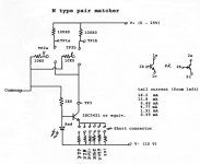
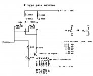
And now, what it actually looks like. It's very crude, but it really works well. I use it far more than I thought I would, so I need to build it properly at some point. I will use the parts I matched again, no use wasting them. They were matched using an HP 34401A and a 4-wire probe setup (nulled) with many averaged readings. Since this is a relative match, the accuracy is very good. I think I'll use the HP 3457A next time, it might do better measuring resistance (again using a 4-terminal, or Kelvin, connection).
Go ahead and build it, it should be easy to do a better job than I did. Note that both the N and P versions are connected together using the same supplies. Makes life a little easier for me.
Now, I should mention that those headers and jumpers set the tail current, and they are additive. The currents are not exact, so I measured them. Maybe I'll become prissy and get the values dead on - maybe. It's not that important really, just measure what the actual currents are so you know.
You will also see that I used 4 terminal in-line sockets (pcb headers) in order to accommodate both US and Japanese transistor pin-outs. Pro-electron pin-outs are a mix of the two and may need to be rotated 180°. Mount the two parts in contact with each other and use a foam cover to shield from air currents and hold the parts together. This thing is extremely basic, so you can add features on the idea (like uP controlled current and voltage + data collection).
A later addition to this perf. board is a jig for matching FM I.F. ceramic resonators, complete with buffers and controlled impedance. That darn perf. board is becoming valuable to me, and crowded too.
Should I build all these jigs into one enclosure, or separate boxes? Darned if I know. The one message is, just build it. It doesn't matter how ugly it becomes, build something and learn!
-Chris
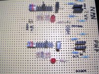
Attachments
janneman said:
Forr,
I believe this scheme is a textbook scheme for an inverting opamp and isn't anything special or inventive.
jd
Barney Oliver used it in his phono section of the integrated amp. The cartridge's (moving magnet) inductance was part of the eq making it all a bit harder to fully comprehend.
The benefit of the inverting connection is that any errors in the amp differential are not part of the process. The amp is only an error amplifier.
John Curl,
First, thanks for taking the time to contribute here on DIYA. There has been some great discussions in this thread and I've appreciated your candor on the JC-1. I have a very quick question that's only a bit off topic...
Some say the current Parasound NewClassic amps (i.e. 2125, 2250, etc.) are your designs. And others say you had nothing to do with them and only the Halo amps are your work.
So what's the *real* answer? Or is it something you can't discuss?
Hi Joshua,
No problem, and my pleasure.
The only thing you have to do is wait for the pair under test to settle down. Time. It would help if you didn't handle the parts directly so they don't heat up, or cool down as the case may be. How hot is it normally there?
I'm open to comments or questions for help. Some people out there may be able to look at it and see if there are any mistakes in method. Whatever helps everyone out is fine.
Hi Jan,

Yup, pretty much!
Mine does have a hidden danger though. You must be very careful where you lay it down to use it. No insulation on perf board wonders! It's only a matter of time before it suffers a failure due to FOD on the bench.
-Chris
No problem, and my pleasure.
The only thing you have to do is wait for the pair under test to settle down. Time. It would help if you didn't handle the parts directly so they don't heat up, or cool down as the case may be. How hot is it normally there?
I'm open to comments or questions for help. Some people out there may be able to look at it and see if there are any mistakes in method. Whatever helps everyone out is fine.
Hi Jan,
We used to call such a contraption a Precison Engineered Special-purpose Testset.
Yup, pretty much!
Mine does have a hidden danger though. You must be very careful where you lay it down to use it. No insulation on perf board wonders! It's only a matter of time before it suffers a failure due to FOD on the bench.
-Chris
hi Chris,
you are a breath of fresh air, not afraid to sketch, knock up and show the 'perf board jig. here. you comments are straightfoward no nosense.
you comment here is classic
''Should I build all these jigs into one enclosure, or separate boxes? Darned if I know. The one message is, just build it. It doesn't matter how ugly it becomes, build something and learn!''
my advise is dont get fancy with it, no box, why bother? if the thing works great throw it in the storage box (s) marked 'jigs'. along with the other hundred or so.
my justification for this attitude is, i know i could improve on it and make it look proffesional but hey im not designing for HP. just for me.
one very important thing is to tie a lable on it, cus you are bound to forget what it does in a few years and keep the drawings etc safe. just like i do, not.
- Status
- Not open for further replies.
- Home
- Member Areas
- The Lounge
- John Curl's Blowtorch preamplifier part II