When designing a producible audio product, we have to take in the 'final' specs first. How much power? What size heatsinks are available? Can we use the 'best' parts?
Then we have to determine how to achieve these specs and still have a reliable product. This entails: Are were going to need circuit protection? How much real 'safe area' do we have in our output devices? Can we fit all the output devices that we might need on the heatsink? etc. etc.
While I follow interesting and exotic circuit designs of others, I usually stick to what I know well, and what 'works' subjectively. Now, I know that some people here think that just about every good measuring amp should sound great, but sometimes, that is not the case. Some of the common 'pitfalls' are low slew rate, not enough peak current, xover distortion, and an overzealous protection circuit. I find that 'complexity' for its own sake, just to get a lower measured static distortion, does not improve the product to the human ear, and even detracts from the overall sonic success of the design. And so forth...
I am pleasantly surprised that the original GD circuit (for the Wall of Sound) that also became the line amp for the JC-2, has become so popular. It is a pretty darn good circuit. Balanced, fast, high open loop, and reasonably linear. For the money, I don't know how to do better, although I do make even more linear line stages in some products, such as the Parasound JC-2, etc. This was the replacement for the OP-Amps of the day, and it still works very well.
Some thoughts from following along your journey in topologies ---- one thing seems never got resolved was the Slew Rate and what differences it made to subjective results.... using very low thd (<-100dB) and same topology. High SR vs minimum (.5v/v - 1v/v).
jFET models are crap and so are many compliment jFEt parts available. A real problem for symmetrical topologies..... causing circuits to get more complicated for low distortion.
Never- the-less, selection of jFETs in the simple circuits is absolutely a requirement for lowest distortion in practice. Relatively simple circuits have produced -120dB levels (measured) with selection and trim. This isnt practical for mass production but it is for DIY or limited production HiEnd construction products.
Since, you, myself and others have shown you can get 'The Numbers' in many forms of circuitry, the circuitry/topology with the fewest parts while maintaining highest performance levels, wins IMO.
THx-RNMarsh
The only matched P/N channel low noise Jfet I could find is U440/441.
Dual monolithic is the only way to go (to keep it simple).
Still ,Jfet's are hard to source ... I tried mosfet P/N pairs. Real good (below)
") .
.They are so easy to find - 20 different choices of both P-channel/N-channel
in matched dual SMD.
DIY'ers lose patience when they can't source (or have to buy a hundred
to test/match).
The reason for my latest "kick" here is that my amp far exceeds my
sources now. Must correct this. Many good -115db attenuators (pga2311).
They only drive 600R loads , but with 2ppm/20K. Need a buffer !
Add a DAC , most of the PGA2311 kits have a extra input just for this.
So , DAC/ 3 more inputs (remote control) and a buffer that can drive
any amp (or headphones).
"GD circuit" - I come up with lots of grateful dead (but no circuit).
OS
Attachments
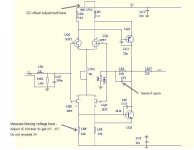
Because of the coin-flip Ben Franklin direction convention for current flow, most like to think of circuits with positive power supplies (as high) and common. This leads to a need for high-side switches most conveniently made from P material and enhanced with gate voltages lower than the switched supply, and as you point out there are a bunch of them now, mostly for low voltage use (the DMOS shown has a 20V Vds max and +/- 8V gate-source limitation). Something to consider if you overdrive the circuit shown---not sure which will "give" first, although gate damage is the worst and irreversible.The only matched P/N channel low noise Jfet I could find is U440/441.
Dual monolithic is the only way to go (to keep it simple).
Still ,Jfet's are hard to source ... I tried mosfet P/N pairs. Real good (below)
They are so easy to find - 20 different choices of both P-channel/N-channel
in matched dual SMD.
DIY'ers lose patience when they can't source (or have to buy a hundred
to test/match).
OS
It seems as if you are using P/N in two different senses above. The U440 is an N channel dual. So I guess "matched P/N channel low noise Jfet" means matched pair... Then "mosfet P/N pairs" means pairs (of single parts, not duals) of P channel and N channel.
Have you looked at low frequency noise for those DMOS parts? The sheer size may mitigate, and processes continue to improve, so it may not be too bad. Of course the manufacturer provides no noise data.
Does anyone know what happened after the introductory distribution of Linear Integrated Systems' LSJ74? I never tried the one piece I got, as I tend to shy from P channel if I don't really need it, and at that I have a fair stock of Toshiba 2SJ74 and even some of the rare 2SJ109 duals.
Brad
Does anyone know what happened after the introductory distribution of Linear Integrated Systems' LSJ74? I never tried the one piece I got, as I tend to shy from P channel if I don't really need it, and at that I have a fair stock of Toshiba 2SJ74 and even some of the rare 2SJ109 duals.
Brad
I built and tested the all FET Shoeps microphone circuit (Pch with optical biasing as output followers) for my article, and it worked quite well. Noise seemed fine.
Ah yes, another reason for P channel (requirements of phantom power).I built and tested the all FET Shoeps microphone circuit (Pch with optical biasing as output followers) for my article, and it worked quite well. Noise seemed fine.
So I guess LIS will just need to get some demand for the part to make another wafer or two.
Because of the coin-flip Ben Franklin direction convention for current flow, most like to think of circuits with positive power supplies (as high) and common. This leads to a need for high-side switches most conveniently made from P material and enhanced with gate voltages lower than the switched supply, and as you point out there are a bunch of them now, mostly for low voltage use (the DMOS shown has a 20V Vds max and +/- 8V gate-source limitation). Something to consider if you overdrive the circuit shown---not sure which will "give" first, although gate damage is the worst and irreversible.
It seems as if you are using P/N in two different senses above. The U440 is an N channel dual. So I guess "matched P/N channel low noise Jfet" means matched pair... Then "mosfet P/N pairs" means pairs (of single parts, not duals) of P channel and N channel.
Have you looked at low frequency noise for those DMOS parts? The sheer size may mitigate, and processes continue to improve, so it may not be too bad. Of course the manufacturer provides no noise data.
Does anyone know what happened after the introductory distribution of Linear Integrated Systems' LSJ74? I never tried the one piece I got, as I tend to shy from P channel if I don't really need it, and at that I have a fair stock of Toshiba 2SJ74 and even some of the rare 2SJ109 duals.
Brad
That's what I am currently researching. The noise at "X" current. This is
the only reason I am even considering a voltage controlled device instead
of the BCxxx's.
I can still hear the BJT junction noise through my headphones. I beat
the hum , semi noise is the "last frontier".
PS - I can always use gate protection in case of overdrive ??
OS
Hackers and painters-by-numbers
PS: I have no idea of the motivation, but diyaudio informs me yesterday that someone was trying to hack my account with a plurality of wrong passwords. The IP address was 117.169.1.110, which looks to be a Far East origination.
I don't know of any enemies over there, but if you see a post alleging to be from me that seems completely anomalous (or at least more than usual ), be skeptical about its authenticity.
Brad
PS: I have no idea of the motivation, but diyaudio informs me yesterday that someone was trying to hack my account with a plurality of wrong passwords. The IP address was 117.169.1.110, which looks to be a Far East origination.
I don't know of any enemies over there, but if you see a post alleging to be from me that seems completely anomalous (or at least more than usual
), be skeptical about its authenticity.Brad
My problem with the PMBFJ620 is the high Idss, coupled with low Yfs.
My problem with PMBFJ620 is huge difference between Vgs (up to 1 Volt)
There is something else mysterious with this part
There are quieter bipolars, at least somewhat, even if the superstars for low rbb' like the 2SA1316 and 2SC3329 are very scarce now.That's what I am currently researching. The noise at "X" current. This is
the only reason I am even considering a voltage controlled device instead
of the BCxxx's.
I can still hear the BJT junction noise through my headphones. I beat
the hum , semi noise is the "last frontier".
PS - I can always use gate protection in case of overdrive ??
OS
Yes, the gates of the DMOS can be protected, although most schemes will introduce some variable capacitances and hence a potential additional distortion mechanism. Biasing a zener and using a small PN diode to isolate until the threshold is reached can help.
Exceeding drain-source Vmax magnitudes will still be a possibility, but that would be rare and usually nondestructive---it's the vulnerable gates that will kill one.
Last edited:
The other thing about bipolars is the noise in the base current, at least full shot noise of 2QeIb per sq rt Hz, with the corresponding parallel noise in JFETs from gate leakage and induced-gate noise much smaller except at extremely high temperatures, or pushing close to breakdown. The induced gate noise is from the thermal channel noise coupling into the gate, and is partially correlated with same, but we can usually ignore it at even high audio frequencies.
I don't know if it is a consequence of stability problems with added poles and zero, or details lost in the labyrinth, but i dink to that.the circuitry/topology with the fewest parts while maintaining highest performance levels, wins IMO.
The other thing about bipolars is the noise in the base current, at least full shot noise of 2QeIb per sq rt Hz, with the corresponding parallel noise in JFETs from gate leakage and induced-gate noise much smaller except at extremely high temperatures, or pushing close to breakdown. The induced gate noise is from the thermal channel noise coupling into the gate, and is partially correlated with same, but we can usually ignore it at even high audio frequencies.
BTW found my 1/f mystery noise, he uses a 2N3819 as an example.
1/f Electrical Noise in Planar Resistors: The Joint
Effect of a Backgating Noise and an
Instrumental Disturbance
José-Ignacio Izpura
2008
Also this from Izpura: http://arxiv.org/ftp/arxiv/papers/1404/1404.6099.pdfBTW found my 1/f mystery noise, he uses a 2N3819 as an example.
1/f Electrical Noise in Planar Resistors: The Joint
Effect of a Backgating Noise and an
Instrumental Disturbance
José-Ignacio Izpura
2008
This will take some time to ponder.
One of the interesting things about 1/f noise is how low it goes, which usually stymies attempts to explain it with given physical models. It seems to have no lower limit, but perhaps in small-enough structures it does.
I want to say, in all honesty, that you guys are all over the map when it comes to low noise design. It isn't as hard as some of you make it out to be, and it isn't obvious either.
Low noise jfets are the easiest devices to get best overall performance, that is over a reasonable impedance range. Some bipolars are quiet, but not many, AND they have to be operated at 1ma or less to have a decent range for a low noise figure. It is easier to use jfets. Mosfets are virtually impossible to make quiet.
Low noise jfets are the easiest devices to get best overall performance, that is over a reasonable impedance range. Some bipolars are quiet, but not many, AND they have to be operated at 1ma or less to have a decent range for a low noise figure. It is easier to use jfets. Mosfets are virtually impossible to make quiet.
I've settled on an AD797 gain stage (c. 16 dB) driving s 5 k log pot configuration followed by a buffer stage. For source impeadance in the 300 to 1.2 k Ohm range it's very hard to beat this device. And you get the ultra low didtortion and high PSRR not available in discrete designs.
For MM phono amps JFETs can offer the lowest noise.
You can read about my effort here Ovation Symphony Line Preamplifier
For MM phono amps JFETs can offer the lowest noise.
You can read about my effort here Ovation Symphony Line Preamplifier
Also this from Izpura: http://arxiv.org/ftp/arxiv/papers/1404/1404.6099.pdf
This will take some time to ponder.
One of the interesting things about 1/f noise is how low it goes, which usually stymies attempts to explain it with given physical models. It seems to have no lower limit, but perhaps in small-enough structures it does.
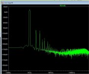
I've measured it to 11uHz (1 cycle/4days) and it holds up almost exactly.
- Status
- Not open for further replies.
- Home
- Member Areas
- The Lounge
- John Curl's Blowtorch preamplifier part II