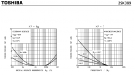
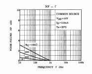
The 6 KHz 1/f corner and best noise match between 10K and 100KOhm really
promises excellent voltage noise behaviour below 10 Hz. No, not really.
Note the huge spread between typ. and guaranteed.
promises excellent voltage noise behaviour below 10 Hz. No, not really.
Note the huge spread between typ. and guaranteed.
Attachments
Last edited:
Which do you recommend?
Hard to say. FETs shine at high impedances and generally have higher 1/f corners.
If you want 2nV/sqrt Hz, that is the noise voltage of a 240 Ohm resistor.
So your source must have less Ohms or you have already lost, even with
an ideal transistor. Transistors that need high source impedance, say > a few 100 Ohms
to avoid adding noise power are therefore no good choice. The 2SK389 is best
at 10 to 100K or so. The noise figure diagram says how much you are punished
if your source imedance is too high or too low.
Bipolars have normally both lower 1/f corners and lower noise _voltages_.
That gives them a head start at low frequencies. The ADA4898 for example has
a 1/f corner of 10 or 20 Hz.
For FETs the white noise is determined by the ratio of gate capacitance and gm.
One always can parallel more transistors, gets bigger gm and less noise.
That is done already on-chip with the Interfet devices, but the C goes trough the roof.
The c/gm ratio of the BF862 is outstanding. IIRC, someone here on diyAudio
has built a monster with 32 transistors or so. I think he needed a small inductor
in the gate connection of each 4 transistors to avoid oscillation.
If it has to be FET, that's probably what I would do.
BF862 are cheap and seem to have a low 1/f corner, at least for the FET league.
But since your source resistance must be < 240 Ohms a priori, the FETs small
noise current is no real advantage.
My preamp with the 10 pairs for sure is extreme, but I wanted something that
I simply can ignore when doing voltage noise measurements on nearly all
interesting objects. The source impedance must be less than abt. 6 Ohm,
but that is OK for voltage references, batteries, regulators or op amp outputs
in PLLs or so. The input impedance of the preamp is still a few KOhm, so
it is no unreasonable load.
And yes, driving the low impedance feedback network is a problem. I got away
with it because I only have small AC voltages in the low noise front stages.
Gerhard
I too wrote for BJT's there's no doubt you can make lower noise circuits with them compared to jfets, however for MC input circuits you have the issue of base currents leaving a potential to be dealt with at the input node, this leaking is not present on jfets making them easier to design with.
This one is better.
Spill the beans then, which one is that??
It seems quite good
We/I want the lowest noise at 10Hz AND lowest distortion as well.
Below, you will understand what I mean by linear device (as per the curve tracer):
The first two are from a very low noise jFET but as you can see the steps are unequally spaced and the horizonal is a soft S shape with curvature at each end. Some point in the middle would be the best choice for a linear (without feedback) performance. The third is from a device which is very linear over a wide range of operating voltages and currents; evenly spaced, flat and horizonal. BUT, it isnt low noise.


THx-RNMarsh
Below, you will understand what I mean by linear device (as per the curve tracer):
The first two are from a very low noise jFET but as you can see the steps are unequally spaced and the horizonal is a soft S shape with curvature at each end. Some point in the middle would be the best choice for a linear (without feedback) performance. The third is from a device which is very linear over a wide range of operating voltages and currents; evenly spaced, flat and horizonal. BUT, it isnt low noise.
THx-RNMarsh
Last edited:
We/I want the lowest noise at 10Hz AND lowest distortion as well.
Below, you will understand what I mean by linear device (as per the curve tracer):
The first two are from a very low noise jFET but as you can see the steps are unequally spaced and the horizonal is a soft S shape with curvature at each end. Some point in the middle would be the best choice for a linear (without feedback) performance. The third is from a device which is very linear over a wide range of operating voltages and currents; evenly spaced, flat and horizonal. BUT, it isnt low noise.
THx-RNMarsh
What are these? (especially the last one). I have not found a JFET with gm invariant with drain current. If it is a bipolar plot of Ic vs Ib this is really apples and oranges. Low noise JFET's have short channels and always look like the top two plots, apply a cascode and they are dead flat. Yes you can cascode them and still put them on your curve tracer and see for yourself.
BTW --- Can you tell me which opamp from AD or other can give me (without requiring 10-20 of them) <2nV/sqrtHz at 10Hz? A couple or few opamps is Ok but not dozens.
To name only a few, all bipolar (you won't find a jfet input).
OPA1612 | Precision Amplifier | Operational Amplifier (Op Amp) | Description & parametrics
AD8599 datasheet and product info | Ultralow Distortion, Ultralow Noise Op Amp (Dual) | Low Voltage Noise Amplifiers (? 10 nV/?Hz) | Analog Devices
MAX9632 36V, Precision, Low-Noise, Wide-Band Amplifier - Maxim
We/I want the lowest noise at 10Hz AND lowest distortion as well.
Below, you will understand what I mean by linear device (as per the curve tracer):
The first two are from a very low noise jFET but as you can see the steps are unequally spaced and the horizonal is a soft S shape with curvature at each end. Some point in the middle would be the best choice for a linear (without feedback) performance. The third is from a device which is very linear over a wide range of operating voltages and currents; evenly spaced, flat and horizonal. BUT, it isnt low noise.
View attachment 463105
View attachment 463106
View attachment 463107
THx-RNMarsh
The third picture is a bipolar transistor, not a jfet.
The third picture is a bipolar transistor, not a jfet.
As I suspected, a truly apples to oranges comparison. The beta vs Ic characteristics have absolutely nothing to do with Ic vs Vbe or in other words the voltage in current out behavior as a input device.
As I suspected, a truly apples to oranges comparison. The beta vs Ic characteristics have absolutely nothing to do with Ic vs Vbe or in other words the voltage in current out behavior as a input device.
Second picture is either a jfet, or a depletion mosfet. Note the Vgs=0 bottom curve, this device has an Idss or u*Cox*W/L. Also note the parabolic shape of the incipient saturation points.
First picture looks like a bipolar close to base punch through condition (so at large Vbc).
What would you use for a (JFET) cascode ?
A self biasing cascode like a J111 (2SK246) / J174 (2SJ103), or a fixed voltage cascode like a bipolar transistor with the base at an elevated voltage ?
What are the pros & cons ?
Patrick
The first looks so easy and uses fewer parts but the low gm high Vp JFET on top still leaves some miller effect OTOH the current transfer is perfect. The bipolar has the lost base current but in the end this can be managed. For real measured performance I doubt it would be that easy to differentiate.
Second picture is either a jfet, or a depletion mosfet. Note the Vgs=0 bottom curve, this device has an Idss or u*Cox*W/L. Also note the parabolic shape of the incipient saturation points.
First picture looks like a bipolar close to base punch through condition (so at large Vbc).
Vgs is not = zero in actuality--- I adjusted the curve tracer to make the first step near zero so you can see all the steps and their spacing. It is a jFET. Bof 'em.
The first two are the same device under different, but not unreasonable, operating conditions. All are at 18vdc max.
Back to the question being avoided --- who makes the lowest noise AND most linear jFET? Does anyone know?
THx-RNMarsh
Last edited:
Vgs is not = zero in actuality--- I adjusted the curve tracer to make the first step near zero so you can see all the steps. It is a jFET. Bof 'em.
The first two are the same device under different, but not unreasonable, operating conditions. All are at 18vdc max.
THx-RNMarsh
Yes, it is easy to build charades, publish incomplete information (scales, step sizes and types, etc...), then let other guess what you mean or intend to show. Must have some entertainment value.
Back to the question being avoided --- who makes the lowest noise AND most linear jFET? Does anyone know?
THx-RNMarsh
Most linear JFET makes no sense, any JFET cascoded has no Vds modulation and the transfer function is square law on all.
There is lots of Vce vs Ib characterization but I never hear anyone talking about Vce vs Vbe (Ib be damned).
I'll set up the curve tracer to show Vce vs Ib
-RNMarsh
Most linear JFET makes no sense, any JFET cascoded has no Vds modulation and the transfer function is square law on all.
Back a few pages I said No cascoding... raw device performance only is what I am looking for. The best performance and lowest noise without cascoding or paralleling etal.
Do you (or anyone) have a recommendation?
-RNM
Last edited:
- Status
- Not open for further replies.
- Home
- Member Areas
- The Lounge
- John Curl's Blowtorch preamplifier part II