The stuff we use is the Rogers 4350 series nicer to work with than the old Teflon back when I did Rf. Nice and stable, doesn't absorb water and solders at high temps. I think it sounds a bit better based on feedback. Apparently other people do also just found out this one won a preamp of the year from TAS.
Those Vendettas still look great today and still a reference.
Proof....
What are you referring to?
Then continues, talking of Trace Antennas, and Trace Reflections - in the latter mentioning the benefit of rounded corners ...17.4.4.1 PCB Trace Characteristics
The layout pattern on a PCB can make it susceptible to radiated noise. A good layout is one that minimizes the susceptibility of analog circuitry to as many radiated noise sources as possible. Unfortunately, there is always a level of RF energy that will be able to upset the normal operation of the circuit. If good design techniques are followed, that level will be one that the circuit never encounters in normal operation.
Which is a key problem - tools acquire more and more "bits", but they typically don't evolve in sophistication, in terms of how they are presented to the user, as they evolve in complexity. Hence, all the really "clever" stuff is often almost unusable, because it requires so much input from the user, the latter has to become an expert in using the program to get the good bits to work ... the tool becomes "dumber", as far as the user is concerned, the more fancy it gets ...
Maybe you aught to use the tools and look at the challenges of todays PCBs...I have a SIV (signal integrity tool) that I use for simulating and checking actual layout for high speed, a power integrity module that lets me assess both DC and AC parameters of the power supplies...On line 3D field solvers for on the fly impedance control of routes as they change layers and thus their relationship to return planes etc. Often boards can take a month or more to lay out due to their complexity...
And it is here where we use all the bloated added on functionality of these tools..
Unusually, I find I have to agree with fas42. I used to be a software developer, and watched with amusement (and some alarm) as management tried various 'silver bullets' which were promised to speed (i.e. dumb down) the development process. I quickly came to the conclusion that software development is an unavoidably creative process so to get good software the primary need is good people - far more important than good tools, although having paid the money for good people it is foolish not to give them good tools too.
The big snag with good tools is that they allow less creative people to bash out some vaguely working software which then gets issued to the customer. This gives management the false impession that writing code is easy, so they employ monkeys and give them lots of typewriters. Later they seem puzzled when the customers complain that the system is unreliable.
Changing tack slightly, I have been involved with writing device drivers for RSX-11M and Windows NT. For RSX (on the PDP-11) I used macro-11 assembler; most of the driver code was for handling the hardware with maybe 10-20% for interfacing with the operating system. For NT (some years later) I used C; most of the driver code was for interfacing with NT with maybe 20% for handling the hardware. I think the earlier driver was a better piece of code and was probably more readable and easier to debug and modify. 'Progress' does not always bring genuine improvements.
One of the reasons that modern websites can be so slow to load is that their developers would not recognise a piece of HTML if it dropped on their foot. Architecture suffers from similar problems, which is why London has suffered from a wobbly bridge (which met all the guidelines for bridge design, but nobody seemed to notice that its resonant frequency was somewhat too close to normal human walking speed) and a solar oven pretending to be an office block.
\end{rant}
Jan,
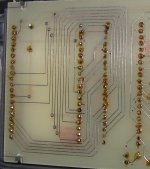
I can describe the way we designed even quite complex and sophisticated multilayer PCB boards in the first half of the eighties (not the simple ones as shown here).
1. step was to prepare large (4:1, e.g.) draft on a special raster paper. This paper might had added aluminum foil inside in order to keep precise dimensions, in case the drawing was used for direct photo and film production. For a digitizer, standard raster paper was enough.
2. step was to use a pointer device, similar to PC mouse, with a window and small cross inside to click on every angle break on the pcb track. These break points were scanned by a digitizer and stored in a memory of a mainframe computer, together with info about trace width and hole diameter and pad diameter.
3. step - output from the mainframe computer was a punched paper tape.
4. step - punched paper tape as an input for drill and photoplotter.
Well you must be happy that we left that period behind us!
")
Maybe you aught to use the tools and look at the challenges of todays PCBs...I have a SIV (signal integrity tool) that I use ...
You're obviously an expert in using such a tool, and that is a highly specialised piece of software, for doing very technical, analytical processing; very mathematical - exactly the sort of situation I'm not talking about ...
Last edited:
Then continues, talking of Trace Antennas, and Trace Reflections - in the latter mentioning the benefit of rounded corners ...
As previously mentioned, this is not a problem below 10GHz, 90, 45 or curved show little difference at lower frequencies, have a look around there is plenty of info regarding this, Howard Johnson has some interesting things to say about it...
With reference to Ti's diagram, you never get a 90 degree corner like that on a PCB, they always have a radii at the corner that is half the trace width.
The text document is from a recent discussion on 90 degree corners...there are many more papers, and interesting that you should refer to this just to have an opposing view, whereas if you had read the document around there , they made a much more critical observation regarding PCB design that you have obviously missed, far more critical than trying to find something that disagrees with the 90 degree corner debate.....
Attachments
Unusually, I find I have to agree with fas42.
It is clear up to this point that (senior) programmers shared the same perspectives. Doesn't mean that it is a correct one, but that we (programmers) see what others (non-programmers) don't.
You're obviously an expert in using such a tool, and that is a highly specialised piece of software, for doing very technical, analytical processing; very mathematical - exactly the sort of situation I'm not talking about ...
The tools do the maths for you, you can get on with the design, these tools are often needed to check a modern day PCB design for signal and power integrity, in fact it is becoming more common with the likes of DDR memory interfaces and fast rise times.
Well you must be happy that we left that period behind us!
I use to prefer standing up doing tape ups and early work with digitisers and a big drawing board, had a smaller waist line and less back ache then as well
Indeed, yes ... that "unavoidably creative" aspect is a bottleneck that seems to be hard to surmount - my desire is for the tools to have enough intrinsic "intelligence" that one only needs to be "creative" in the areas where something genuinely new and different is required - "re-engineering" the same programming structures, over and over again, is no laughing matter ....I quickly came to the conclusion that software development is an unavoidably creative process so to get good software the primary need is good people - far more important than good tools, although having paid the money for good people it is foolish not to give them good tools too.}
One of the reasons that modern websites can be so slow to load is that their developers would not recognise a piece of HTML if it dropped on their foot.
People still use HTML?
Well you must be happy that we left that period behind us!
Definitely, but, on the other hand, we were closer to the real process and had to think everything over in deep.
Well, I'm interested in the recent conversation about "programming methodology". I've always had an interest in programming but have never gotten very far. It could be that high level languages just don't make a single speck of sense to my brain, so I try to learn assembly as my first language:
flat assembler - View topic - Circle gone wrong
I did eventually get that circle drawing program to work:
flat assembler - View topic - Circle gone wrong
But I stalled again trying to figure out how to use the multithreading syscalls. I have been working on other things since.
flat assembler - View topic - Circle gone wrong
I did eventually get that circle drawing program to work:
flat assembler - View topic - Circle gone wrong
But I stalled again trying to figure out how to use the multithreading syscalls. I have been working on other things since.


I don't know if I'll have to make my own, John. The Luxman C-03 preamp has quite a phono stage, which I haven't tried out yet due to the builders not wanting to leave me, but I will of course. If it lives up to its hype, I won't have to.
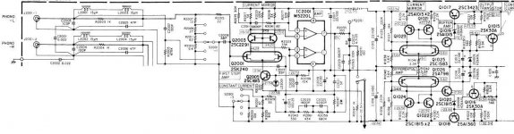
Any obvious explanation as to why they use ½ of this dual op amp IC and leave the other ½ dormant instead of a) paralleling the two op amps for to increase the current out or b) use a single op amp IC from the beginning?
Remember the Voyager computer: General Electric 18-bit TTL machine with a bit-serial, single register accumulator and bit-serial access to plated-wire RAM (4096 words). 25,000 instructions per second. To reach the limits of the known universe.
Low speed serial computer operation (and data transmition) was intentional.
They had to cater for the bursts of charged-particles radiation up there.
Low number of bits per second operation meant more contained data damage per (random) radiation burst, with the hope that the error correction algorithms could successfully reconstruct the data strings from the remainder.
Well, I still use ORCAD
There, that shows how old I am!
EAGLE anyone?
George
Attachments
Last edited:
- Status
- Not open for further replies.
- Home
- Member Areas
- The Lounge
- John Curl's Blowtorch preamplifier part II