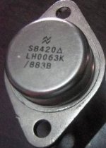
Your buffer is almost ideal, Esperado. It comes from a hybrid device that National Semi offered in the 1960's called the LH0002, that was in a TO-5 IC package.
Nice thing about that chip is that it was fast enough that you could insert it after an op amp and take the feedback from its output. I built a few preamps out of it and they worked very well indeed. It was also available in DIP- I think I still have half a dozen of those in my junk box.
DVV may prefer one with more horsepower.

Yeah, well, I can't help it. In general, I think I qualify as a realist, in the middle between an optimist and a pessimist (who is an optimist with experience), but when it comes to audio, I am so pessimistic you could even call me a darker and not be wrong. I have nightmares of evil, complex loads wreaking havoc on my output stage.
I think it's all AR's fault. Much as I liked and still do like some of their speakers, they always were difficult loads to drive, and some models, like AR 3a Improved, were downright criminal loads. This has led me to develop a taste for currant capable amplifiers, which could manage the speakers properly, even according to fas42 standards. When I started to put them together myself, you could bet your bottom dollar/euro/florin/drachma/Turkish lira that if anything, it would be able to dump a lot of current. If it didn't sound right, it was not for lack of current capability, I messed up someweher else. My dream of heaven has God handing me a 1 Farad capacitor from a bag full of them.
I realize that I'm probably overdoing it with the whole PSU business, but I figure more can't hurt, but too little can.
There's something perversly reassuring when you look at a nominally 100/200W into 8/4 Ohms amp and see two 500 VA toroids, plus a third toroid for the split supplies. Morally, I feel I have the basic human right to have a character flaw - I don't gamble, I don't drink, I don't chase women, I don't saw wild oats, I don't do drugs, it just ain't normal to have no flaw. So, PSUs are my flaw and I wear it with pride.
Last edited:
Morally, I feel I have the basic human right to have a character flaw - I don't gamble, I don't drink, I don't chase women, I don't saw wild oats, I don't do drugs, it just ain't normal to have no flaw. So, PSUs are my flaw and I wear it with pride.
Have you ever considered to exchange the last one for all the others? Seems like a whole lot more fun
Flaws? Nah, I never even tried drugs, I was always afraid to do so because I might have liked it too much.
Not that I had no opportunity, mind you, I've been to Amsterdam four times in the last 8 years. In one cafe, the owner gave me a dirty look when I lit one of my Danesmann cigarillos, it must have looked suspricious to him. Then, when he brought my espresso and got a whiff of it, he smiled.
I mention Amsterdam because I believe joints are legal there, but I notice cafes declare themselves as pro joint or anti joint with little stickers - right? Fortunately, beer is legal everywhere.
I think that it is a very important topic, and this thread is the right place to find a right answer. Too many contradictions here.It is very well known that increasing the reservoir caps will increase both the level and order of the harmonics on the supply line. That gives a lot of scope to have an audible effect, depending on several factors.
Nothing 'magical' here...
Jan
Audio experts, it is your turn.
Your buffer is almost ideal, Esperado.
Except that, as drawn, the output pair works in class C
. Output voltage is DC zero, opamp output is DC zero, hence assuming Vbe identical for npn and pnp devices, the current through the 15 ohm resistors is exactly zero. In practice, it may be slightly larger, since the driver devices are biased, and hence may have Vbe larger than the output devices. Anyway, far from any optimum bias.In ICs is a different story, emitter areas ratio may take care of the output pair bias.
Last edited:
Actually, the colour rendition, of a particular TV set, is a pretty good analogy to what I'm talking about ... you walk into someone's house, who has an expensive video setup - and immediately, a snap judgement by your visual senses, is that the colour balance is badly out of whack. The bloke who owns it can yabber on for hours about its brilliant spec's, and if you mention that it doesn't "look right" then he might demand "technical measurements" to "prove" that it's not right - but no matter what he says, if it doesn't look right, then it's not right - simple as that.That is cos subjective hearing is perception and like trying to judge white balance by eye can be easily fooled......
But then I'm just a blind deaf and dumb kid....
That's exactly how I judge the sound - there's a sense of rightness about what I'm hearing, always, if it's working correctly ... even if I'm completely distracted, and only listening out of the corner of my ear, and it's just background filler - it still sounds right. And in that same vein, when a TV set has poor colour balance, then it is always caught out - something is shown which you're very familiar with, say a flower that you have in the garden, or a vegetable - and to your eyes the colour is miles out, it just looks fake.
The subjective works very well, if it is asked to judge whether something is realistic, or convincing - you're looking for defects, flaws; not comparing "goodnesses" ...
Last edited:
Have-you any notion of electronic and specially the base emitter offset in a bjt?the current through the 15 ohm resistors is exactly zero.

Oh ! No current in a diamond ? That's brand new.
Last edited:
Have-you any notion of electronic and specially the base emitter offset in a bjt?
Oh ! No current in a diamond ? That's brand new.
You ought to prove some knowledge and common sense and add resistors in the input diamond pair. I would then probably have nothing to comment, the output devices bias current will stand in the emitter resistors ratio.
You did not, that's why I said "as drawn". In fact, I believe you took the LH0002 schematic without any elementary inspection analysis and a minimum understanding on how ICs work.
DVV may prefer one with more horsepower.
Well if you're going to drive those 50 Watt headphones you need the Big Iron!
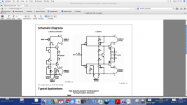
Arf, this very classical buffer is used since decades in a lot of well regarded studio's gears. Used to feed any Lundahl 600/600 line transformer. Current is around 3mA on first stage, 1.5mA-2mA in the second one. Depending of the emitter resistances used. Output impedance is so low that you can even use symmetrical not shielded cables with no audible hum. And it 'sound' very good.You did not, that's why I said "as drawn". In fact, I believe you took the LH0002 schematic without any elementary inspection analysis and a minimum understanding on how ICs work.
Like in this one: http://www.soundonsound.com/sos/sep12/articles/gp-pml200e.htm
It is easy to figure out in real life: understand-it, build-it, measure-it. Or just sim-it. That you seems to never do. I can understand the reasons: Your main occupation seems to be dedicated to harass me, answering stupid things against each and every of my posts on this forum.
As answered John Curl, both your "your class C" and "exactly zero" is just a prove of your total lack of understanding and plain wrong.
And guess what ? I never used or looked to any LH2002 schematics. But i stay very interested to see the schematic of one of your productions, one day or an other ?
Attachments
Last edited:
Arf, this very classical buffer is used since decades in a lot of well regarded studio's gears.
Hundreds of post were dedicated in this thread to complaints about ICs under biasing the output stage, and the lack of Class A ICs.
And now, a discrete buffer that has a chronically under biased output stage (at 1-2mA) got praised as the best thing since sliced bread. Figure out.
And of course, conveniently skipping and quoting posts could not miss into this mix:
In practice, it may be slightly larger, since the driver devices are biased, and hence may have Vbe larger than the output devices. Anyway, far from any optimum bias.
In ICs is a different story, emitter areas ratio may take care of the output pair bias.
And then again, you seem to miss the fact that in an IC implementation, the output current is adjusted primary by adjusting the emitter areas ratio. Something its not really possible in a discrete implementation. That's how all these IC buffers are designed and built in silicon.
Harassing you was never intended. Harassing your obvious misinformation always was.
2Esperado
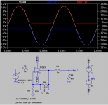
Sorry, but you can do it with the same performance quite without discrete output stage (working in class B with about 1,5mA quiescent current, relying on NFB from LT1363), it is useless. LT1363 is all you need. It is unity gain stable, able to work in 600ohm load with full swing (output current +-25mA), stable in capacitive load...
Sorry, but you can do it with the same performance quite without discrete output stage (working in class B with about 1,5mA quiescent current, relying on NFB from LT1363), it is useless. LT1363 is all you need. It is unity gain stable, able to work in 600ohm load with full swing (output current +-25mA), stable in capacitive load...
understand-it, build-it, measure-it
Attachments
Last edited:
2Esperado
Sorry, but you can do it with the same performance quite without discrete output stage (working in class B with about 1,5mA quiescent current, relying on NFB from LT1363), it is useless. LT1363 is all you need. It is unity gain stable, able to work in 600ohm load with full swing (output current +-25mA), stable in capacitive load...
But you don't know whether that 5mA bias is in the output stage or in the pre-stages or bias network...
Jan
- Status
- Not open for further replies.
- Home
- Member Areas
- The Lounge
- John Curl's Blowtorch preamplifier part II