I have not found anything like this (or bandwidth curves of open loop).
I'm sure you have a sim file for your amps: it is so easy to trace the bandwidth at the input of the VAS, closed loop. !
Well, i don't believe it is possible to do a lot better, unless using a lot of local feedback, so very low GNFB ratio.
Flat up to 60KHZ ? i don't believe-it.
The feedback comp ensign, and the LTspice loop gain plots are described in some detail in section 4 starting at page 23. The LTspice plot says it's 60 kHz and there are very good reasons why it is so wide.
http://hifisonix.com/wordpress/wp-content/uploads/2014/10/The-sx-Amplifier-V2.09.pdf
Last edited:
Ok But we know that. David just said he tried the suggested IC circuit as his first circuit he tried.--- didnt cut muster for him. Need better..... David cant stand the idea that a buffer amp on the output of his high super clean osc will reduce the performance of his hard work.
We need the best design ever that money can buy/build.
THx-RNMarsh
We need the best design ever that money can buy/build.
THx-RNMarsh
This buffer achieves 30ppb@10Vpp@100KHz and has been built and tested (not the THD figure, it comes from sim)He wants it for an instrument - not as a headphone amp, so what it sounds like is not important - as long as it's sub -130 dB.
It is temperamental, but usable:
http://www.diyaudio.com/forums/solid-state/260454-unstable-buffer-8.html#post4031679
Helping the guys tweak the demo card Friday, as I was saying they farkled to grounding scheme.
Hey Scott, had an extensive listening session with the AD815 power amp last Friday. Including very sensitive horn speakers. They had to lower the tweeter level which made it clear that his super-duper tube amp rolled off the highs...
Comments on the AD815 included total absence of sibilance and very clean top compared to their own stuff.
Jan
Attachments
I have increased total capacitance in my phono preamp Blowtorch-like raw power supply from 4700 micro to 6800 same brand and type of capacitors.
I left 24hours for burn-in. But sonic results are not good-sound is degraded with lack of precision , loss of fine details and with a false body of instruments.
It seems that Pavel is right when he suggesting not to go over the top with capacitors in preamps power supplies. He uses humble 1000 micro in his regulated power supply. Perhaps some people like coloration which high value capacitors provide-it reminds me of microphonic valve type of coloration.
Kamis, if you want more capacitance, I suggest you take a different approach, which is to parallel smaller value of capacitors. Two ways come to mind.
Sometime in the late 70ies, I read a text in some magazine about some people making a preamo using 24 680 uF caps. When asked why exactly that value and why exactly so many, one of the designers frankly admitted they had no idea, but it seemed to work best out of many versions they tried. That's the try-it-and-see approach.
The other is Sony's approach. For their top of the line models, they normally use two caps in parallel for each supply line, consisting of one large value, say 4,700 uF and another of same make but of say 2,200 uF. The tehory is that larger caps filter better in the audio band but are slower than smaller caps, which filter less well but have the speed advantage.
You also might try this: after the last cap, solder a 1 Ohm 1W resistor in series with 470 nF polypropylene from each power line to the ground. This should get rid of residual inductance and may show us as audibly better speed and cleaner treble. The best part is, you can retrofit this to anything, so long as you find space for the added components.
I know what you're on about, because of that effect I always use 2 2,200 uF caps in parallel rather than 1 4,700 uF cap per each supply line.
Almost everybody excessively loads the outputs with both the feedback resistors and the external load with lower than optimum impedance..........
Interesting observation and quite a sweeping statement.
Do you have any rule of thumb for this, you know, a sweet spot... a value you wouldn't normally go below impedance wise given a typical voltage feedback device ?
Kamis, if you want more capacitance, I suggest you take a different approach, which is to parallel smaller value of capacitors. Two ways come to mind.
Sometime in the late 70ies, I read a text in some magazine about some people making a preamo using 24 680 uF caps. When asked why exactly that value and why exactly so many, one of the designers frankly admitted they had no idea, but it seemed to work best out of many versions they tried. That's the try-it-and-see approach.
The other is Sony's approach. For their top of the line models, they normally use two caps in parallel for each supply line, consisting of one large value, say 4,700 uF and another of same make but of say 2,200 uF.
I know what you're on about, because of that effect I always use 2 2,200 uF caps in parallel rather than 1 4,700 uF cap per each supply line.
In fact, I have 3300+2200-1000 low ESR caps. per rail and 1000 micro 100V floating between +and-. Without 33oo micro sound was better. There is 100n film capacitor on every rail.
What about high charging currents and stress on the bridge of large caps?
I trust my ears.
It is sad to see people criticizing Ron Quan's research even without reading the latest paper carefully.
Of course, this goes with the territory, and we had the same problem with TIM, back in the 1970's.
It be remembered that there are 3 stages to an idea (or a new approach to measurement in this case).
1. The problem doesn't exist.
2. The problem perhaps exists, but it isn't important. (where we are today)
3. We invented it.
This is a universal prediction that has been proven thousands of times, over history.
Ron Quan does not just do PIM or similar measurements. He also finds other problems with IC's as they are made today.
It is true that the latest or most expensive IC's usually have less of what he is trying to measure, and he frequently admits it, but first he has to show a change in the distortion compared to just THD, or even 2 tone IM. He has to start somewhere with a 'typical' example. His latest 'example' is a 1458, which is a very old part, BUT still mentioned frequently on this website. He starts there, but as his measurements become more refined, I predict that many more modern parts will show measurable deviations from ideal, as well.
My phono preamp raw power supply have the same CLC topology as Parasound JC-2 schematics( Blowtorch?) you attached here. My CM chokes have 100mH.I have found that: All else being equal, more capacitance is better than less capacitance, at least up to 20,000uF for a preamp.
I think that 22000 micro after chokes is too high.
I have increased total capacitance in my phono preamp Blowtorch-like raw power supply from 4700 micro to 6800 same brand and type of capacitors.
I left 24hours for burn-in. But sonic results are not good-sound is degraded with lack of precision , loss of fine details and with a false body of instruments.
It seems that Pavel is right when he suggesting not to go over the top with capacitors in preamps power supplies. He uses humble 1000 micro in his regulated power supply. Perhaps some people like coloration which high value capacitors provide-it reminds me of microphonic valve type of coloration.
It is very well known that increasing the reservoir caps will increase both the level and order of the harmonics on the supply line. That gives a lot of scope to have an audible effect, depending on several factors.
Nothing 'magical' here...
Jan
Interesting observation and quite a sweeping statement.
You're too kind
jan
I 've used the indirect IMD difference, long averaging with gain for the error product to get -160 dB nonlinearity measurement resolution, could see, had to fix NPO distortion in Sallen-Key filter by replacing with polystyrene
passive component linearity, layout parasitics are the real limitation with well implemented multiloop, something like OPA627 (I'd try OPA827 today) wrapped around TPA6120
and Esperado seems confused - high open loop bandwidth can just be a sign of poor DC gain - not "speed"
many CFA op amps do have limited 70-80 dB open loop Vgain and show "flat" open loop gain up to 100 kHz
AD797 can be decompensated to quite respectable 100 MHz GBW (actually up to 450 MHz GBW @ Acl 1000) but has Avol over 10^6, 5-10 million typical, giving "low open loop bandwidth" with a Avol corner frequency of few 10s Hz
http://www.analog.com/static/imported-files/data_sheets/AD797.pdf
I believe for audio power amps today the limitation is output device speed with some mosfet limited by packaging RF parasitics of common TO-247 or similar
Last edited:
This buffer achieves 30ppb@10Vpp@100KHz and has been built and tested (not the THD figure, it comes from sim)
It is temperamental, but usable:
http://www.diyaudio.com/forums/solid-state/260454-unstable-buffer-8.html#post4031679
No wonder, this is the Rush cascode, something not for the faint hearted (when it comes to stability). A dozen of other topologies (pushed at the marginal stability at unity gain) can deliver the same.
What do you gents think of this?
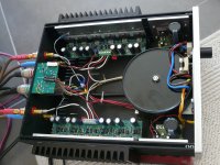
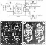
This design was published in 1990 or '91 in a German magazine. It was designed by Dr Herman Holger, working for Burr-Brown in Germany.
Op amp 1 is OP 37, op amp 2 is a 50V/uS op amp, I don't remember the designation. It's adaptable for both MM and MC.
This design was published in 1990 or '91 in a German magazine. It was designed by Dr Herman Holger, working for Burr-Brown in Germany.
Op amp 1 is OP 37, op amp 2 is a 50V/uS op amp, I don't remember the designation. It's adaptable for both MM and MC.
Attachments
I think that 2K and higher TOTAL load resistance is optimum.
I would probably have thought of 2k as getting toward the low side of things. Anyhow that's useful to know, thanks.
- Status
- Not open for further replies.
- Home
- Member Areas
- The Lounge
- John Curl's Blowtorch preamplifier part II