Bonsai, at around the same time as you mention, I was listening to a pair of AR 5 speakers. Basically very similar to AR 3a Improved, but bass driver was not 12" but 10", while nominal impednce was not 4 but 8 Ohms.
In spite of all that, the ARs were still rather choosy speakers, not all amps could drive them well. At the time, I was based on a reVox A78 integrated amp (nominally 40/50W into 8/4 Ohms), and on the side, I also used my own version of the Otala/Lohstroh amp (25/50W into 8/4 Ohms), and by 1979, I also had a version of the German LAS Mega 1 amp (100/160W into 8/4 Ohms, but capable of around 20A impulse current).
I also had severa Bose models as guests several times, from 301 to 90x.
In my view, while Bose was more spacious than AR, it was way behind AR in all other aspects. To me, they were an interesting experiment which fell short on execution, meaning that I think they should have used 2 way speakers, with at least 3 dome tweeters, because to me they were most lacking in the treble range.
Something along the lines of Thorens Sound Wall speakers, which played that game much more convincingly than Bose (but were also much bigger).
You certainly couldn't measure for CE testing with that setup it just doesn't have the range.
As I am looking at the moment at preamp level power supplies none of the devices make enough noise for CE to worry about. Hooking my rf analyzer directly to the PC Card any switching noise was below my analyzer's noise limit.
So I will have to do the same test on a higher power circuit.
What do you measure the diode noise with? Do you place this device across R3?
A plain and simple scope shows the switching nicely. I have used an rf spectrum analyzer for other diode noise measurements.
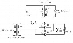
The frequency range of that trafo is 200Hz-15KHz. Seems to me it would distort the switching glitches at high frequencies, and add it's own ring.
Don't believe the data sheet. Everyone I measured was way better.
Now does anyone want to guess the dominant frequency of the rectification/switching frequencies?
Scott
You are talking about the low resonant frequency of each speaker unit and the spread of it in a production line, yes?
No you highlighted it, a technically very cavalier statement about speaker aberations averaging out even though each speaker is nominally the same .
statistical matching ....No you highlighted it, a technically very cavalier statement about speaker aberations averaging out even though each speaker is nominally the same .
http://www.ti.com/lit/an/snoa626b/snoa626b.pdf
Well since things are quiet again, here is my circuit for testing diode switching noise. Open for questions and comments.
I have an instrument which uses similar idea- transformers for both DMode and CM measurements and presents a low voltage output of what noise is on the line(s). Or, my Fluke 43A sometimes for up to 15th harmonic and PF of 50-60Hz testing. Or, use a wideband clamp on current probe/meter/spectrum analyzer.
I have seen a lot of the noise on the ac input side to equipment. But not just diode/rectifier noise is coming from our beloved connected equipment (audio, video and computer and others on the ac line).
THx-RNMarsh
Last edited:
Well since things are quiet again, here is my circuit for testing diode switching noise. Open for questions and comments.
It looks like, in effect, you have a current probe. I find a magnetic field probe more useful in both looking at the transient waveforms and seeing how far they radiate. What I see suggests the tank circuit of the transformer self resonance and the cap around the diodes has more impact than the diodes seem to themselves. More distressing is how far the fields can go.
We need some ideas for a decent DIY Magfield probe. They pop up on eBay occasionally but not often.
Demian
I started with a magnetic probe!
Yes I am looking at current. The output is reasonably well behaved with the 620 ohm termination resistor. Different diodes shown different results.
The main issue is turn on resonances. Most of the real diode switch noise literature is for switching power supplies. When you have 1000 nS of switch off time on a 40kHz switcher you spray lots of energy into the ether as it has no where to go. At 120 Hz you have about 3% of that energy floating around.
The turn on energy does have a place to go so since it isn't launched into the ether regulators don't worry about it. It instead rattles around the power line at a level ten times as much energy as switch off. Now as the load capacitor is only coupled to the transformer inductance during the charging portion of the AC cycle a lot of resonant energy goes back into the power line. A simple snubber will take care of much of the switch on energy and diode bypasses can handle the switch off in a low current power supply.
Now in a high current supply charging can be quite different
The issue becomes transformer vs capacitor bank to provide adequate power without undue noise.
I think you saw my two transformer technique to clean up common mode noise.
But the real issue is I am having a very hard time measuring in circuit switching noise from low current power supplies.
One common comment is that a well designed power supply should be able to remove line noise issues. As Dick has pointed out many times the amount of noise on a normal power line is very significant. As he does not live under a transmitter tower, there are even worse places.
So this issue is just how much do diodes really matter, how to snub transformers and diodes and avoid creating or passing noise.
So far I am three years in on my power supply article and most of the general knowledge is really not useful for many designs.
Demian,
Almost forgot a simple mag field probe is shown in an old LT ap note. It is ten turns of 34 gauge wire around a 50 ohm resistor inside a slotted brass tube. One end is soldered to the tube the other end goes to the center pin if a female bnc. The brass tube is ground. An amplifier with a gain if at least 100 is needed. It can be as simple as four AD797s cascaded. Each set for a gain of 3.16 using low value feedback resistors. That should also give a bandwidth of at least ten MHz. (Bypass Bypass Bypass and a bit of interstage shielding wouldn't hurt)
Almost forgot a simple mag field probe is shown in an old LT ap note. It is ten turns of 34 gauge wire around a 50 ohm resistor inside a slotted brass tube. One end is soldered to the tube the other end goes to the center pin if a female bnc. The brass tube is ground. An amplifier with a gain if at least 100 is needed. It can be as simple as four AD797s cascaded. Each set for a gain of 3.16 using low value feedback resistors. That should also give a bandwidth of at least ten MHz. (Bypass Bypass Bypass and a bit of interstage shielding wouldn't hurt)
Have you looked at synchronous rectifiers? Basically switch some big FETs on at the right time. I see the technique used in high power switchmode supplies to get lower losses and more controlled switching. For 60 Hz it could work really well if a reasonable control circuit can be invented. Conceptually either a phase shifted transformer or maybe some diodes could switch the FETs on at the right time. I know this stuff is never as easy as it looks but the FET's would have a controlled turn on and turn off reducing the resonances.
Here is some more on the technique: http://www.fairchildsemi.com/an/AN/AN-6208.pdf
You could even use them as a form of regulator. Many years ago I met a guy who was designing power supplied for mainframes. He was using SCR's for the regulation. He said that when you have 100A current the inductors get pretty small and still work. In this the FET's would be doing the same thing.
When you have 1000 nS of switch off time on a 40kHz switcher you spray lots of energy into the ether as it has no where to go.
That's an awfully slow diode to select for a 40 khz smps. I'd expect it to get too hot.
edit: Ed, why the 10 ohm resistor? That tends to dull out the transients.
How about using a nice 100 milliohm zero magfield resistor? I'd be happy to make you one if you wish.
jn
Last edited:
Demian,
Synchronous rectifiers are the way to go for high power, been a fan for decades! However the issue is turn on surge. It actually is not quite as abrupt as it is a sine wave feeding the capacitor at the phase angle where the slew rate begins to slow. Now on turn off the transformer has less load so the internal losses drop and the voltage rises. Even though the voltage rises the current supplied to the capacitor drops, so at turn off there is not very much current. That is quite different than in a square wave switcher.
J.N.
I don't know why you would object to a 1000 nS diode for a 40 kHz switcher. It would only waste just under 30% of the total power!")
As to the resistor value after getting the range of output values it can be lowered to still give nice pictures. The transformer currently being used is good to about 200 kHz. Now for the next generation of tests I will be able to go to 20 MHz. But for now the data is interesting.
Synchronous rectifiers are the way to go for high power, been a fan for decades! However the issue is turn on surge. It actually is not quite as abrupt as it is a sine wave feeding the capacitor at the phase angle where the slew rate begins to slow. Now on turn off the transformer has less load so the internal losses drop and the voltage rises. Even though the voltage rises the current supplied to the capacitor drops, so at turn off there is not very much current. That is quite different than in a square wave switcher.
J.N.
I don't know why you would object to a 1000 nS diode for a 40 kHz switcher. It would only waste just under 30% of the total power!
As to the resistor value after getting the range of output values it can be lowered to still give nice pictures. The transformer currently being used is good to about 200 kHz. Now for the next generation of tests I will be able to go to 20 MHz. But for now the data is interesting.
Simon,
If I am following this last discussion correctly your last test setup is only for measurement purposes. How would you incorporate your thinking into a low powered power supply, would this be a linear power supply you are talking about or a regulated supply, I am assuming for the moment it is not a smps. Can you show a circuit diagram of how you would actually approach a solution in a simple power supply?
If I am following this last discussion correctly your last test setup is only for measurement purposes. How would you incorporate your thinking into a low powered power supply, would this be a linear power supply you are talking about or a regulated supply, I am assuming for the moment it is not a smps. Can you show a circuit diagram of how you would actually approach a solution in a simple power supply?
- Status
- Not open for further replies.
- Home
- Member Areas
- The Lounge
- John Curl's Blowtorch preamplifier part II