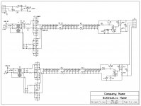
Like this for a low noise preamp power supply. I use one of these in my JC3 clone. I hear no power line artifacts even with my ear nest to the loudspeaker.
P.S. J.C. doesn't like this design it is too complicated. Sometime soon I will finish tweaking it and post measurements. The goal is to be quieter than a battery.
P.S. J.C. doesn't like this design it is too complicated. Sometime soon I will finish tweaking it and post measurements. The goal is to be quieter than a battery.
Attachments
Last edited:
Like this for a low noise preamp power supply. I use one of these in my JC3 clone. I hear no power line artifacts even with my ear nest to the loudspeaker.
P.S. J.C. doesn't like this design it is too complicated. Sometime soon I will finish tweaking it and post measurements. The goal is to be quieter than a battery.
Best batteries approach -200dBV a number even you will like.
Best batteries approach -200dBV a number even you will like.
And just how do you measure that?
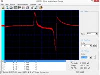
Attached are three shots of 1N4007 diodes in the test setup. First no snubber, then a 1 uF snubber across the transformer secondary and last snubber with 12,000 uf more capacitance. traces offset high by two divisions to show largest display possible. Ch. 2 looks at AC out of transformer to get trigger.
Note that even with the much larger filter capacitor the charging current is the same.
I do have a design for a low distortion oscillator, but have no idea how to adjust it!
Attachments


Last edited:
Ed, that is a good supply, but it takes more time and effort to make, because it has so many parts. IF the cap quality is essentially similar, I would concentrate the caps to a simpler configuration, and add common mode chokes.
Actually I could use fewer caps and they should be different values at each stage. But I will wait to play with that when I finish building the equipment I need to properly test a supply that works this poorly.
Cross correlating amplifier and a lot of time.And just how do you measure that?
http://tf.nist.gov/general/pdf/1133.pdf
I have seen that paper and stole a bit from it for my power supply article. I'll just send you one when I finish and you can let me know.
")
Demian,
This is the ap note that shows how to build current probes.
http://cds.linear.com/docs/en/application-note/an70.pdf
This is the ap note that shows how to build current probes.
http://cds.linear.com/docs/en/application-note/an70.pdf
Wow! Built out of parts that you can get for free.
I am having a hard time trying to measure impedances of .1-10R with an injection current of no more than 20mA, at 1-25MHz. I'm trying to use a Tektronix FG504 and a 465B scope.
Maybe one of you guys knows a good way to do this? Ground and power cable antenna resonances are goofing everything up. The 25MHz spike disappears when I put my hand on the variac.
Maybe one of you guys knows a good way to do this? Ground and power cable antenna resonances are goofing everything up. The 25MHz spike disappears when I put my hand on the variac.
At those frequencies you need a network analyzer or a vector impedance meter, HP 4193 or HP 4815 (pretty rare, Richard Marsh has one). Any other method will prove to be really difficult because of the phase issues. If you are measuring power lines it will be far more difficult since the line is a bunch of mismatched segments all resonating at many different frequencies.
I did some work on power line networking and came to realize that its not a stable link. The PLN stuff actively rechecks the line conditions every 45 degrees or so of the mains frequency since it changes a lot and switches carrier frequencies almost that fast. The latest generation uses up to 65 MHz and can get as far as 200'. It can push as much as 5A of RF into the line to do this.
What are you trying to find out? I may have been there already.
For that you do need a network analyzer or its equivalent. You could use a VSWR bridge and a sensitive amp and you may get what you want to see. Here is a DIY directional coupler/VSWR bridge http://www.ve2azx.net/technical/RLBridges.pdf They also pop up on eBay. You will also need an RF short and termination to "calibrate" it. It can quickly get as involved as audio, fortunately far less subjective.
That page gives a link to this page -
Fundamentals of EMC Design: Our Products Are Trying To Help Us
Required reading !.
Dan.
I am having a hard time trying to measure impedances of .1-10R with an injection current of no more than 20mA, at 1-25MHz. I'm trying to use a Tektronix FG504 and a 465B scope.
Maybe one of you guys knows a good way to do this? Ground and power cable antenna resonances are goofing everything up. The 25MHz spike disappears when I put my hand on the variac.
I had big problems like you, due to ground loops, HF resonances of the interconnecting cables and the like.
Try to use an equipment that incorporates both the signal generator and the detector. It helps in eliminating pick-up loops.
What I have found that greatly helps is a signal generator/detector unit in which the detector has a steep bandpass tracking filter synchronized to the sweeping frequency of the generator.
Then, it’s the characterization of the test jig (it’s cable, each single component and every complete test jig )
http://www.diyaudio.com/forums/everything-else/250441-jneutron-influence-consequences.html
Would a spectrum analyzer be much different from doing a frequency sweep with a sine generator?
It would be the same in terms of the above problems.
But it will show you better the resonances that plague these measurements and will help you identify and locate them.
Ed, Scott, Demian, Richard, Dan, thank you for the links.
George
Like this for a low noise preamp power supply. I use one of these in my JC3 clone. I hear no power line artifacts even with my ear nest to the loudspeaker.
Hi Ed
Is your system ground completely disconnected from mains ground, connected to mains ground or decoupled somehow from mains ground ?
When putting a cap across the line / mains, I found that adding 1R in series measured better in spice and sounded better in reality - although, with all those decoupling caps in ur supply you may not notice any difference - but other equipment connected to the mains may be affected by the resonance. The second line cap is decoupled from the line inductance so the 1R is not needed.
I try to avoid any circuit that could generate a High Q resonance.
Last edited:
Hi Ed
Is your system ground completely disconnected from mains ground, connected to mains ground or decoupled somehow from mains ground ?
When putting a cap across the line / mains, I found that adding 1R in series measured better in spice and sounded better in reality - although, with all those decoupling caps in ur supply you may not notice any difference - but other equipment connected to the mains may be affected by the resonance. The second line cap is decoupled from the line inductance so the 1R is not needed.
I try to avoid any circuit that could generate a High Q resonance.
The transformers are on an internal chassis that is then insulated from the outer case. This gives me an IEC & UL compliant insulated system. The current code is aimed at eliminating the ground connection from consumer gear.
Some time back I did an Audioxpress article on setting up a resonant circuit on the AC power line. The circulating currents were enough to melt the resonant capacitor tuning switches rated at 30 amps. So adjustments had to be made with the power turned off. So your suggestion of a small resistor in series with the first capacitor seems to be a good one.
- Status
- Not open for further replies.
- Home
- Member Areas
- The Lounge
- John Curl's Blowtorch preamplifier part II